Sharp MX-5500N / MX-6200N / MX-7000N (serv.man45) Service Manual ▷ View online
MX-7000N ADJUSTMENTS 6 – 2
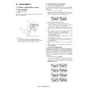
3. Details of adjustment
ADJ 1
Developing doctor gap
adjustment (For color)
adjustment (For color)
This adjustment must be executed in the following cases:
* When the developing unit is disassembled.
* When the print image density is low.
* When there is a blur on the print image.
* When there is unevenness in the print image density.
* There is abnormally much toner dispersion.
1)
* When the developing unit is disassembled.
* When the print image density is low.
* When there is a blur on the print image.
* When there is unevenness in the print image density.
* There is abnormally much toner dispersion.
1)
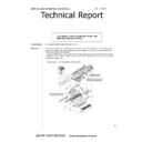
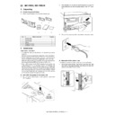
Remove the developing unit from the main unit, and remove
the developing unit upper cover and the developing doctor
cover.
the developing unit upper cover and the developing doctor
cover.
2)
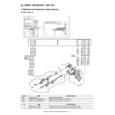
Loosen the developing doctor fixing screw.
3)
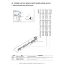
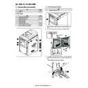
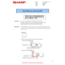
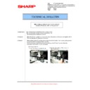
Insert a thickness gauge of 0.40mm between 40mm – 70mm
from the edge of the developing doctor.
from the edge of the developing doctor.
4)
Push the developing doctor in the arrow direction, and tighten
the fixing screw of the developing doctor. (Perform the similar
procedure for the front frame and the rear frame.)
the fixing screw of the developing doctor. (Perform the similar
procedure for the front frame and the rear frame.)
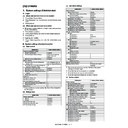
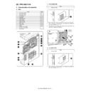
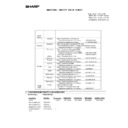
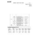
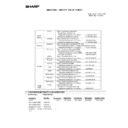
ADJ 22
Copy color balance/density adjustment
22I
Gamma/density adjustment in the text image edge section (Normally not required)
46-27
22J
Copy color balance adjustment (Single color copy mode) (Normally not required)
46-25
22K
Auto color balance adjustment by the user (Copy color balance auto adjustment
ENABLE setting and adjustment)
ENABLE setting and adjustment)
26-53
22L
Background process condition setting in the color auto copy mode
46-33
22M
Color document identification level (ACS operation) setting
46-33
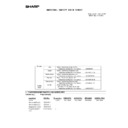
ADJ 23
Printer color balance/density
adjustment
adjustment
23A
Printer color balance adjustment (Auto adjustment)
67-24/44-26
23B
Printer color balance adjustment (Manual adjustment)
67-25/44-26/
67-27/67-28
67-27/67-28
23C
Auto color balance adjustment by the user (Printer color balance auto adjustment
ENABLE setting and adjustment)
ENABLE setting and adjustment)
26-54
ADJ 24
Fusing paper guide position adjustment
ADJ 25
Document size sensor adjustment
25A
Document size sensor detection point adjustment
41-1
25B
Document size sensor sensitivity adjustment
41-2
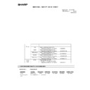
ADJ 26
Manual paper feed tray paper size (width) sensor adjustment
40-2
ADJ 27
DSPF paper feed tray paper size (width) sensor adjustment
53-6
ADJ 28
Touch panel coordinate setting
65-1
ADJ 29
Image loss, void area, image off-
center, image magnification ratio auto
adjustment with SIM50-28
center, image magnification ratio auto
adjustment with SIM50-28
29A
Print image main scanning direction image magnification ratio automatic adjustment
50-28
29B
Image off-center automatic adjustment
50-28
29C
Copy lead edge image reference position adjustment, image off-center, sub scanning
direction image magnification ratio automatic adjustment
direction image magnification ratio automatic adjustment
50-28
29D
DSPF mode auto void adjustment (Service installation adjustment)
50-28
ADJ 30
Shading adjustment
63-2
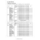
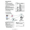
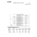
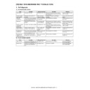
Job No.
Adjustment item list
Simulation
40mm
70mm
40mm
70mm
MX-7000N ADJUSTMENTS 6 – 3
5)
Check that the doctor gaps at two positions in 40mm – 70mm
from the both sides of the developing doctor are in the range of
0.40
from the both sides of the developing doctor are in the range of
0.40
± 0.05mm.
* When inserting a thickness gauge, be careful not to scratch the
developing doctor and the developing roller.
ADJ 2
Developing roller main pole
position adjustment (For color)
position adjustment (For color)
This adjustment must be executed in the following cases:
* When the developing unit is disassembled.
* When the print image density is low.
* When there is a blur on the print image.
* When there is unevenness in the print image density.
* There is abnormally much toner dispersion.
1)
* When the developing unit is disassembled.
* When the print image density is low.
* When there is a blur on the print image.
* When there is unevenness in the print image density.
* There is abnormally much toner dispersion.
1)
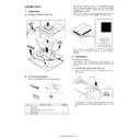
Remove the developing doctor cover, and place the develop-
ing unit on a flat surface.
ing unit on a flat surface.
2)
Attach a thread to a needle or a pin.
3)
Hold the thread and bring the needle near the developing
roller. (Do not use a paper clip because it will not provide a cor-
rect position.)
roller. (Do not use a paper clip because it will not provide a cor-
rect position.)
4)
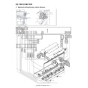
Mark the developing roller surface on the extension line of the
needle with the needle at 2 – 3mm from the developing roller
surface. (Never touch the needle tip with the developing roller.)
needle with the needle at 2 – 3mm from the developing roller
surface. (Never touch the needle tip with the developing roller.)
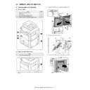
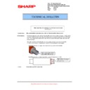
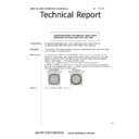
5)
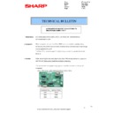
Measure the distance between the marking position and posi-
tion A of the developing unit frame, and check that it is 37.8
tion A of the developing unit frame, and check that it is 37.8
±
0.5mm.
If the distance is not within the above range, adjust the devel-
oping roller main pole position in the following procedures.
If the distance is not within the above range, adjust the devel-
oping roller main pole position in the following procedures.
6)
Remove the developing unit front cover, loosen the fixing
screw of the developing roller main pole adjustment plate, and
move the adjustment plate in the arrow direction to adjust.
screw of the developing roller main pole adjustment plate, and
move the adjustment plate in the arrow direction to adjust.
Repeat procedures 3) – 6) until the developing roller main pole
position comes to the specified range.
position comes to the specified range.
7)
After completion of the adjustment of the developing roller
main pole position, fix the developing roller main pole adjust-
ment plate with the fixing screw.
main pole position, fix the developing roller main pole adjust-
ment plate with the fixing screw.
ADJ 3
Developing doctor gap
adjustment (For black)
adjustment (For black)
This adjustment must be executed in the following cases:
* When the developing unit is disassembled.
* When the print image density is low.
* When there is a blur on the print image.
* When there is unevenness in the print image density.
* There is abnormally much toner dispersion.
1)
* When the developing unit is disassembled.
* When the print image density is low.
* When there is a blur on the print image.
* When there is unevenness in the print image density.
* There is abnormally much toner dispersion.
1)
Remove the developing unit from the main unit, and remove
the developing unit upper cover and the developing doctor
cover.
the developing unit upper cover and the developing doctor
cover.
2)
Loosen the developing doctor fixing screw.
40mm
70mm
40mm
70mm
2㨪3mm
37.8+0.5mm
A
37.8+0.5mm
MX-7000N ADJUSTMENTS 6 – 4
3)
Insert a thickness gauge of 0.45mm between 40mm – 70mm
from the edge of the developing doctor.
from the edge of the developing doctor.
4)
Push the developing doctor in the arrow direction, and tighten
the fixing screw of the developing doctor. (Perform the similar
procedure for the front frame and the rear frame.)
the fixing screw of the developing doctor. (Perform the similar
procedure for the front frame and the rear frame.)
5)
Check that the doctor gaps at two positions in 40mm – 70mm
from the both sides of the developing doctor are in the range of
0.45
from the both sides of the developing doctor are in the range of
0.45
± 0.05mm.
* When inserting a thickness gauge, be careful not to scratch the
developing doctor and the developing roller.
ADJ 4
Developing roller main pole
position adjustment (For black)
position adjustment (For black)
This adjustment must be executed in the following cases:
* When the developing unit is disassembled.
* When the print image density is low.
* When there is a blur on the print image.
* When the developing unit is disassembled.
* When the print image density is low.
* When there is a blur on the print image.
* When there is unevenness in the print image density.
* There is abnormally much toner dispersion.
1)
* There is abnormally much toner dispersion.
1)
Remove the developing doctor cover, and place the develop-
ing unit on a flat surface.
ing unit on a flat surface.
2)
Attach a thread to a needle or a pin.
3)
Hold the thread and bring the needle near the developing
roller. (Do not use a paper clip because it will not provide a cor-
rect position.)
roller. (Do not use a paper clip because it will not provide a cor-
rect position.)
4)
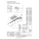
Mark the developing roller surface on the extension line of the
needle with the needle at 2 – 3mm from the developing roller
surface. (Never touch the needle tip with the developing roller.)
needle with the needle at 2 – 3mm from the developing roller
surface. (Never touch the needle tip with the developing roller.)
5)
Measure the distance between the marking position and posi-
tion A of the developing unit frame, and check that it is 62.1
tion A of the developing unit frame, and check that it is 62.1
±
0.5mm.
If the distance is not within the above range, adjust the devel-
oping roller main pole position in the following procedures.
If the distance is not within the above range, adjust the devel-
oping roller main pole position in the following procedures.
6)
Remove the developing unit front cover, loosen the fixing
screw of the developing roller main pole adjustment plate, and
move the adjustment plate in the arrow direction to adjust.
screw of the developing roller main pole adjustment plate, and
move the adjustment plate in the arrow direction to adjust.
Repeat procedures 3) – 6) until the developing roller main pole
position comes to the specified range.
position comes to the specified range.
7)
After completion of the adjustment of the developing roller
main pole position, fix the developing roller main pole adjust-
ment plate with the fixing screw.
main pole position, fix the developing roller main pole adjust-
ment plate with the fixing screw.
40mm
70mm
70mm
40mm
40mm
70mm
70mm
40mm
2
㨪3mm
62.1 0.5mm
+
62.1 0.5mm
+
A
MX-7000N ADJUSTMENTS 6 – 5
ADJ 5
Toner density control reference
value setting
value setting
This adjustment must be executed in the following cases:
* When developer is replaced.
* When developer is replaced.
NOTE: Be sure to execute this adjustment only when developer is
replaced. Never execute it in the other cases.
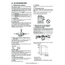
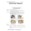
1)
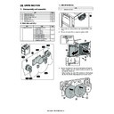
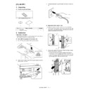
With the front cover (lower) open, enter SIM25-2.
2)
Close the front cover (lower).
3)
Select a developing unit to be adjusted.
4)
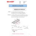
When [EXECUTE] key it pressed, it is highlighted. The devel-
oping roller rotates, and the toner sensor detects toner density,
and the output value is displayed.
The above operation is executed for 3 minutes, and the aver-
age value of the toner density sensor detection level is set
(saved) as the reference toner density control value.
When the reference toner density control adjustment operation
is completed, [EXECUTE] key display return, to normal from
highlight. This makes you know whether the adjustment opera-
tion is completed or not.
The above operation is executed each of the lower speed
mode, the middle speed mode and the high speed mode, and
the reference toner density control value is set for each of
them.
NOTE: If the operation is interrupted within 3 minutes, the
adjustment result is not reflected (enabled).
When [EXECUTE] key is pressed during rotation, the opera-
tion is stopped and [EXECUTE] key returns to the normal dis-
play.
If [EE-EU], [EE-EL], or [EE-EG] is displayed, setting of the ref-
erence toner density control value is not completed normally.
tion is stopped and [EXECUTE] key returns to the normal dis-
play.
If [EE-EU], [EE-EL], or [EE-EG] is displayed, setting of the ref-
erence toner density control value is not completed normally.
5)
Use SIM24-5 to clear the developer counter.
6)
Use SIM44-27 to clear the half-tone correction data.
NOTE:
1)
1)
When replacing developer, always replace all the three colors
of Yellow, Magenta, and Cyan.
If only one color is replaced, color balance may be adversely
affected. Black developer can be replaced individually.
of Yellow, Magenta, and Cyan.
If only one color is replaced, color balance may be adversely
affected. Black developer can be replaced individually.
2)
After replacement of developer or the photoconductor, be sure
to execute SIM44-27 to clear the half-tone correction data.
If the above procedure is neglected, the half-tone correction
may not be performed correctly.
to execute SIM44-27 to clear the half-tone correction data.
If the above procedure is neglected, the half-tone correction
may not be performed correctly.
ADJ 6
High voltage adjustments
6-A
Main charger grid voltage adjustment
This adjustment must be executed in the following cases:
* When the MC/DV high voltage power PWB is replaced.
* When U2 trouble occurs.
* When the PCU PWB is replaced.
* When EEPROM on the PCU PWB is replaced.
* When the MC/DV high voltage power PWB is replaced.
* When U2 trouble occurs.
* When the PCU PWB is replaced.
* When EEPROM on the PCU PWB is replaced.
EXECUTE
M
K
Adjustment completed
EXECUTE
Abnormal end
Y
C
AUTOMATIC DEVELOPER ADJUSTMENT
EXECUTE
TCD_K
45
:
1/1
SIMULATION NO.25-02
TEST
CLOSE
TCV_K
45
:
TCD_C
50
:
TCD_M
50
:
TCD_Y
45
:
TCV_C
50
:
TCV_M
50
:
TCV_Y
50
:
M
K
M
Y
C
K
AUTOMATIC DEVELOPER ADJUSTMENT
EXECUTE
AT DEVE ADJ_L_K
128
:
AT DEVEVO_L_Y
128
:
1/1
SIMULATION NO.25-02
TEST
CLOSE
AT DEVE ADJ_M_K
128
:
AT DEVE VO_M_Y
128
:
AT DEVE ADJ_L_C
128
:
AT DEVE VO_M_K
128
:
AT DEVE ADJ_L_M
128
:
AT DEVE VO_M_C
128
:
AT DEVE ADJ_L_Y
128
:
AT DEVE VO_M_M
128
:
AT DEVE ADJ_M_C
128
:
AT DEVE VO_H_K
128
:
AT DEVE ADJ_M_M
128
:
AT DEVE ADJ_M_Y
128
:
AT DEVE ADJ_H_K
128
:
AT DEVEVO_L_K
128
:
AT DEVEVO_L_M
128
:
AT DEVEVO_L_C
128
:
or process interrupt
Y
C
AUTOMATIC DEVELOPER ADJUSTMENT
EXECUTE
TCD_K
EE-EL
:
1/1
SIMULATION NO.25-02
TEST
CLOSE
TCV_K
:
TCD_C
50
:
TCD_M
EE-EL
:
TCD_Y
45
:
TCV_C
:
TCV_M
:
TCV_Y
:
M
K
M
Y
C
K
AUTOMATIC DEVELOPER ADJUSTMENT
EXECUTE
AT DEVE ADJ_L_K
185
:
AT DEVEVO_L_Y
128
:
1/1
SIMULATION NO.25-02
TEST
CLOSE
AT DEVE ADJ_M_K
185
:
AT DEVE VO_M_Y
128
:
AT DEVE ADJ_L_C
128
:
AT DEVE VO_M_K
185
:
AT DEVE ADJ_L_M
185
:
AT DEVE VO_M_C
128
:
:
AT DEVE ADJ_L_Y
128
:
AT DEVE VO_M_M
185
AT DEVE ADJ_M_C
128
:
AT DEVE VO_H_K
128
:
AT DEVE ADJ_M_M
185
:
AT DEVE ADJ_M_Y
128
:
AT DEVE ADJ_H_K
185
:
AT DEVEVO_L_K
185
:
AT DEVEVO_L_M
185
:
AT DEVEVO_L_C
128
:
Error
display
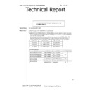
Error name
Detail of error
Remark
EE-EL
EL
abnormality
abnormality
(1) The sensor output level is less
than 0.5V in 1min after execution
of SIM25-02.
than 0.5V in 1min after execution
of SIM25-02.
When either
of (1) or (2)
is satisfied.
of (1) or (2)
is satisfied.
(2) The sensor output level is less
than 1.5V after the adjustment for
each speed or the control voltage
exceeds 8.0V.
than 1.5V after the adjustment for
each speed or the control voltage
exceeds 8.0V.
EE-EU
EU
abnormality
abnormality
(1) The sensor output level
exceeds 4.5V in 1min after
execution of SIM25-02.
exceeds 4.5V in 1min after
execution of SIM25-02.
When either
of (1) or (2)
is satisfied.
of (1) or (2)
is satisfied.
The sensor output level exceeds
3.45V after the adjustment for
each speed or the control voltage
is less than 2.0V.
3.45V after the adjustment for
each speed or the control voltage
is less than 2.0V.
EE-EC
EC
abnormality
abnormality
The sensor output level after the
adjustment for each speed is not
2.5V
adjustment for each speed is not
2.5V
± 0.2V.

