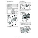
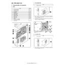
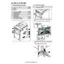
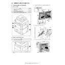
Sharp MX-5500N / MX-6200N / MX-7000N (serv.man17) Peripheral ▷ View online
MX-FNX4 OPERATIONAL DESCRIPTION 5 – 1
MX-FNX4
Service Manual
[5] OPERATIONAL DESCRIPTION
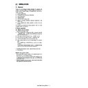
1. Basic operation
A. Basic operation of finisher
The finisher is designed to deliver copies arriving from its host
machine, and its modes of delivery include simple stacking, job off-
set, and staple.
All operations involved in these modes are controlled by the fin-
isher controller PCB, according to the appropriate commands from
the host machine.
In the case of the Saddle stitch finisher, copies from the host
machine may be routed to the saddle stitch unit.
NOTE: The term job offset refers to shifting each sorting job, sepa-
rating a single stack into several stacks.
B. Outline of electric circuitry in finisher
The finisher's sequence of operation is controlled by the finisher
controller PCB. The finisher controller PCB is a 16-bit microproces-
sor (CPU), and is used for communication with the host machine
(serial) in addition to controlling the finisher's sequence of opera-
tions.
The finisher controller PCB responds to the various commands
coming from the host machine through a serial communications
line to drive solenoids, motors, and other loads. In addition, it com-
municates the finisher's various states (information on sensors and
switches) to the host machine through a serial communications cir-
cuit.
In the case of the Saddle Finisher, the finisher controller PCB not
only communicates with the saddle stitch controller PCB but also
communicates the saddle stitch unit's various states (information
on sensors and switches) to the host machine.
The ICs used on the finisher controller PCB are designed for the
following:
• IC2 (CPU)
Controls sequence of operations/sequence program built-in.
• IC3 (EEP-ROM)
For backup of adjustment values/backup of default data.
• IC28 (Regulator IC)
Generates 5V.
• IC7 (Regulator IC)
Generates 3.3V.
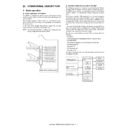
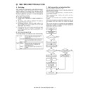
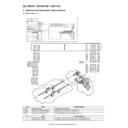
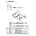
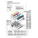
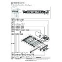
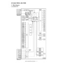
The figure below shows the flow of signals between the finisher and
the optional controller.
the optional controller.
Tray drive system
Tray drive system
Control
system
Swing guide drive system
Alignment drive system
Stapler drive system
Delivery drive system
Feed drive system
Shutter drive system
Saddle stitch unit control system
Saddle stitch
controller PCB
Punch controller
PCB
(Punch module(option))
Host machine
(DC controller PCB CPU)
Finisher controller
PCB
IC2
CPU
IC3
EEP-ROM
IC28
Regulator IC
IC7
Regulator IC
Motor
Solenoid
Switch
Sensor
Sensor
MX-FNX4 OPERATIONAL DESCRIPTION 5 – 2
C. Basic operation of saddle stitcher (MX-FNX4)
The unit "stitches" (2 points) a stack of sheets delivered by the fin-
isher and folds it in two for delivery. All these operations are con-
trolled by the saddle stitch controller PCB in response to
commands from the host machine via the finisher.
isher and folds it in two for delivery. All these operations are con-
trolled by the saddle stitch controller PCB in response to
commands from the host machine via the finisher.
D. Outline of electric circuitry in saddle stitch unit
(MX-FNX4)
The sequence of operations used for the saddle stitch unit is con-
trolled by the saddle stitch controller PCB. The saddle stitch con-
troller PCB has a microprocessor. This microprocessor is used to
control the sequence of operations and to handle serial communi-
cations with the finisher controller PCB, driving solenoids and
motors in response to the various commands from the finisher con-
troller PCB.
The saddle stitch controller PCB is also used to communicate the
state of various sensors and switches to the finisher controller PCB
in serial.
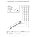
The functions of the major ICs mounted on the saddle stitch con-
troller PCB are as follows:
• IC7 (CPU)
Controls sequence of operations/sequence program built-in.
• IC8 (IC)
Communicates with the finisher.
• IC512 (Regulator IC)
Generates 5V.
• IC10 (Regulator IC)
Generates 3.3V.
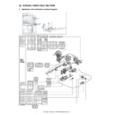
E. Inputs to and outputs from the punch control
PCB (option)
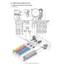
Inputs to and outputs from the punch control PCB
Outputs from the punch control PCB
Finisher control system
Control
system
Guide plate drive system
Paperpositioningplatedrivesystem
Alignment drive system
Saddle stitch drive system
Delivery drive system
Feed drive system
Paper pushing plate
drive system
Paper folding roller
drive system
Sensor
Switch
Saddle stitch
controller PCB
IC7 CPU
IC512
Regulator IC
IC10
Regulator IC
IC8
IC
Finisher controller
PCB
Host machine
Motor
Solenoid
Punch motor
lock sensor
When the punch slide
unit is at home position,
'1'.
While the punch motor
is rotating,alternates
between '0' and '1'.
Waste full PCB(FPDD)
When the light is
blocked,'0'.
When paper is
detected,'0'.
FPFDD
FPUDSW
Punch
front door
Punch
upper cover
J602-1
-3
J622-1
-2
J621-1
-2
-4
-6
FRONT COVER
+24V
UP COVER
+24V
FPHPD
FPSHPD
FPE
J613-1
-2
-3
J611-1
-2
-3
J612-1
-2
-3
J605-A3
-A2
-A1
J605-A7
-A9
-A8
J605-A6
-A5
-A4
J606-1
-2
-3
-4
J618-4
-3
-2
-1
J605-B6
-B5
-B4
-B3
-B2
-B1
-B7
J615-2
-3
-4
-5
-6
-7
-1
+5V
PUNCH
+5V
SLIDE
+5V
CLOCK
SREG1*
SREG2*
SREG3*
SREG4*
PAEND*
DUSTLED
DUSTPTR
+5V
+5V
+5V
PT1
PT131
LED121
PT2
PT3
PT4
PT5
Punch home
position sensor
Horizontal
registration
home position
sensor
Punch control PCB
When the hole puncher is
at home position,'0'.
Horizontal registration photosensor PCB (FPTD)
J604-1
-2
-3
-4
J619-6
-4
-3
-1
A*
A
B
B*
FPNM
FPSM
FSIFM
J605-B13
-B8
-B9
-B10
-B11
-B12
J614-1
-6
-5
-4
-3
-2
J603-1
-2
J620-1
-2
J605-A10
-A11
-A12
-A13
J610-1
-2
-3
-4
J610-4
-3
-2
-1
A
B
A*
B*
LEDON5
LEDON4
LEDON3
LEDON2
LEDON1
+5V
LED5
LED4
LED3
LED2
LED1
Horizontal registration LED PCB (FPSD)
Punch control PCB
When '1',LED goes ON.
Punch motor
Punch horizontal registration motor
Punch transport motor
Switches between '+' and '-'
according to the direction of
motor rotation.
Switches the pulse
signals according to
the rotation of the motor.
Switches the pulse
signals according to
the rotation of the motor.
MX-FNX4 OPERATIONAL DESCRIPTION 5 – 3
2. Feed/drive system
A. Outline
This machine comprises the finisher and the saddle stitch unit.
The finisher is designed to operate according to the commands
from its host machine to deliver arriving copies to trays in the
appropriate mode: simple stacking, job offset, or stapling. The sad-
dle stitch unit folds paper stack and delivers it to the delivery tray of
the saddle stitch unit after feeding, aligning, stitching, and feeding
the paper supplied from the host machine in accordance with the
commands received through the finisher controller PCB. Four deliv-
ery modes are available.
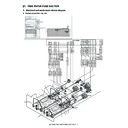
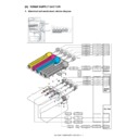
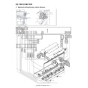
B. Control configuration of finisher
The finisher moves copies arriving from the host machine to the
delivery tray, stapling tray, or the saddle stitch unit according to the
mode of delivery. On the stapling tray, the copies are subjected to
job offset or stapling as instructed by the host machine.
In addition, stack is delivered from the stapling tray with the help of
the trailing edge assist guide as well as the delivery roller. The inlet
motor (FFM), delivery motor (FAM), and the trailing edge assist
motor (FASM) are the stepping motors. These motors are con-
trolled by the microprocessor (CPU) on the finisher controller PCB,
and rotate either clockwise or counterclockwise.
The paper paths are equipped with the following two sensors for
detection of paper (arrival, passage):
• Inlet sensor (FED)
• Feed path sensor (FPDD)
In addition, each delivery tray is equipped with a sensor designed
to detect the presence/absence of paper on it.
• No.1 tray paper sensor (FBED1)
• No.2 tray paper sensor (FBED2)
If a copy fails to reach or move past each sensor within a specific
period of time, the finisher controller PCB identifies the condition as
a jam, and stops the ongoing operation, and at the same time,
informs the host machine of the condition. When all doors are
closed after the paper jam is removed, the above two sensors (inlet
sensor and delivery path sensor) check whether or not copies are
being detected. If the sensors detect a copy, the finisher unit judges
that paper jams have not completely been removed, and sends the
paper jam removal signal to the host machine again.
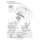
Delivery
system
Normal
delivery
Saddle stitch delivery
Job offset
Staple
Simplestacking
*One-pointstapleinthefront
*One-pointstapleattheback
*Two-pointstaple
Normal delivery tray
Normal delivery tray
Saddle stitch
delivery tray
Finisher controller PCB (1/2)
No.2
tray
shift
motor
drive
signal
No.1
tray
shift
shift
motor
drive
signal
Stack
delivery
motor
drive
signal
signal
Alignment
front/back
m
otor
drive
signal
Tr
ailing
edge
assist
assist
motor
drive
signal
Inlet
m
otor
drive
signal
Saddle
inlet
m
otor
drive
signal
Stapler
shift
m
otor
drive
drive
signal
Stapler
m
otor
drive
drive
signal
No.1
delivery
roller
separator
solenoid
drive
signal
Buf
fer
roller
separator
fer
roller
separator
solenoid
drive
signal
signal
Inlet
roller
separator
separator
solenoid
drive
signal
Buf
fer
trailing
fer
trailing
edge
holding
solenoid
drive
signal
Saddle
inlet
selector
solenoid
drive
signal
signal
Finisher controller PCB (2/2)
Saddle stitcher
controller PCB
Saddle driver
PCB
FTLM2
FTLM1
FAM
FASM FFM
FSIFM
FSM
FFSM
FFJM
FRJM
FBES
FSFS
FINRRS
FBRRS
FFDRRS
MX-FNX4 OPERATIONAL DESCRIPTION 5 – 4
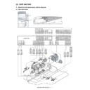
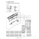
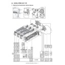
C. Delivery path of finisher
Outline
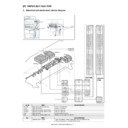
Three types of delivery paths to the tray 1/2 of this machine are
available, depending on the processes of the paper delivery.
Straight delivery
If sort job is not to be implemented, all the paper is delivered
through the path shown in the figure below.
Three types of delivery paths to the tray 1/2 of this machine are
available, depending on the processes of the paper delivery.
Straight delivery
If sort job is not to be implemented, all the paper is delivered
through the path shown in the figure below.
Path to stapling tray
If the sort job of paper in other than A4, B5, or LTR size or the sta-
ple sort is to be implemented, delivered paper passes through this
path. After paper is fed to the stapling tray, it is aligned and stapled.
Then, it is delivered with the help of the trailing edge assist.
If the sort job of paper in other than A4, B5, or LTR size or the sta-
ple sort is to be implemented, delivered paper passes through this
path. After paper is fed to the stapling tray, it is aligned and stapled.
Then, it is delivered with the help of the trailing edge assist.
Path to buffer/stapling tray
If the sort job of paper in A4, B5, or LTR size or the staple sort is to
be implemented, delivered paper passes through this path. After
two sheets (if stitching is to be performed at two points, two or three
sheets) are delivered to the buffer, they are aligned at the stapling
tray, stapled, and then discharged. Since paper is delivered from
the host machine continuously, paper fed to the buffer can be
simultaneously delivered together with stack paper that has been
already stapled at the stapling tray even while stapling or offset
operation is being carried out. Stack paper delivered from the buffer
is fed to the stapling tray, and paper stapled at the stapling tray is
fed to the tray.
If the sort job mode is selected, the simultaneous delivery of two
sheets of A4 size paper in paper stacks is described as shown
below.
Finisher controller PCB
No.2
tray
paper
paper
detection
signal
TR
Y2-P
Y2-P
No.1
tray
paper
paper
detection
signal
TR
Y1-P
Y1-P
Feed
path
paper
detection
signal
TIMING
Inlet
paper
paper
detection
signal
INLET
Tray
Paper
Stack delivery
roller
No.1 delivery
roller
Buffer roller
Inlet roller
Paper
Stack delivery
roller
No.1 delivery
roller
Buffer
roller
Inlet roller
Paper
Stapling tray
Trailing edge assist

