|
|
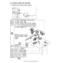
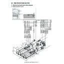
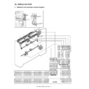
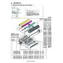
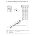
MX-5500N MX-6200N MX-7000N (serv.man41)
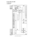
Circuit Diagram
Service Manual
|
127
|
21.31 MB
|
|
|
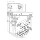
MX-5500N MX-6200N MX-7000N (serv.man42)
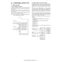
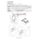
Product Outline
Service Manual
|
3
|
221.33 KB
|
|
|
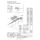
MX-5500N MX-6200N MX-7000N (serv.man43)
Consumable Parts
Service Manual
|
6
|
194.79 KB
|
|
|
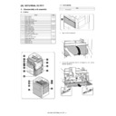
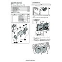
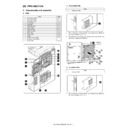
MX-5500N MX-6200N MX-7000N (serv.man44)
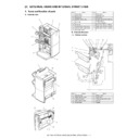
External View Internal Structure
Service Manual
|
19
|
1.97 MB
|
|
|
MX-5500N MX-6200N MX-7000N (serv.man45)
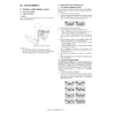
Adjustments
Service Manual
|
76
|
6.43 MB
|
|
|
MX-5500N MX-6200N MX-7000N (serv.man46)
Simulation
Service Manual
|
127
|
3.61 MB
|
|
|
MX-5500N MX-6200N MX-7000N (serv.man47)
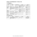
Self diagnostics Trouble Codes
Service Manual
|
33
|
322.94 KB
|
|
|
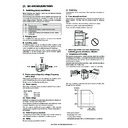
MX-5500N MX-6200N MX-7000N (serv.man48)
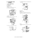
Maintenance
Service Manual
|
16
|
2.12 MB
|
|
|
MX-5500N MX-6200N MX-7000N (serv.man49)
ROM Version Up
Service Manual
|
3
|
485.71 KB
|
|
|
MX-5500N MX-6200N MX-7000N (serv.man50)
Electrical Section
Service Manual
|
51
|
1.02 MB
|
|
|
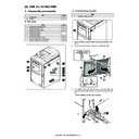
MX-5500N MX-6200N MX-7000N (serv.man51)
Others
Service Manual
|
9
|
933.37 KB
|
|
|
MX-5500N MX-6200N MX-7000N (serv.man52)
Paper transport Section-Detailed Section
Service Manual
|
20
|
4.83 MB
|
|
|
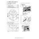
MX-5500N MX-6200N MX-7000N (serv.man53)
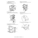
External Outfit-Detailed Section
Service Manual
|
8
|
2 MB
|
|
|
MX-5500N MX-6200N MX-7000N (serv.man54)
Operation Panel-Detailed Section
Service Manual
|
4
|
675.4 KB
|
|
|
MX-5500N MX-6200N MX-7000N (serv.man55)
DSPF Section-Detailed section
Service Manual
|
39
|
9.91 MB
|
|
|
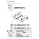
MX-5500N MX-6200N MX-7000N (serv.man56)
Scanner Section-detailed Section
Service Manual
|
10
|
1.81 MB
|
|
|
MX-5500N MX-6200N MX-7000N (serv.man57)
Manual Paper Feed Section-Detailed Section
Service Manual
|
10
|
2.53 MB
|
|
|
MX-5500N MX-6200N MX-7000N (serv.man58)
Tray Paper Feed Section-Detailed Section
Service Manual
|
23
|
6.76 MB
|
|
|
MX-5500N MX-6200N MX-7000N (serv.man59)
Duplex Section-Detailed section
Service Manual
|
17
|
6.45 MB
|
|
|
MX-5500N MX-6200N MX-7000N (serv.man60)
LSU Section-Detailed section
Service Manual
|
10
|
1.69 MB
|
|
|
MX-5500N MX-6200N MX-7000N (serv.man61)
Detailed Section
Service Manual
|
16
|
3.83 MB
|
|
|
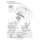
MX-5500N MX-6200N MX-7000N (serv.man62)
Toner Supply Section-Detailed section
Service Manual
|
5
|
2.45 MB
|
|
|
MX-5500N MX-6200N MX-7000N (serv.man63)
Developing Section-Detailed Section
Service Manual
|
13
|
3.47 MB
|
|
|
MX-5500N MX-6200N MX-7000N (serv.man64)
Transfer Section-Detailed Section
Service Manual
|
18
|
6.08 MB
|
|
|
MX-5500N MX-6200N MX-7000N (serv.man65)
Process Control Sensor Reg sensor Section-Detailed Section
Service Manual
|
4
|
653.25 KB
|
|
|
MX-5500N MX-6200N MX-7000N (serv.man66)
Fusing Section-Detailed section
Service Manual
|
25
|
8.05 MB
|
|
|
MX-5500N MX-6200N MX-7000N (serv.man67)
Paper Exit Section-Detailed section
Service Manual
|
7
|
1.08 MB
|
|
|
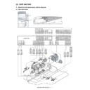
MX-5500N MX-6200N MX-7000N (serv.man68)
Drive Section-Detailed Section
Service Manual
|
32
|
8.87 MB
|
|
|
MX-5500N MX-6200N MX-7000N (serv.man69)
Pwb Section-Detailed section
Service Manual
|
8
|
1.73 MB
|
|
|
MX-5500N MX-6200N MX-7000N (serv.man70)
Fan Filter Section-Detailed section
Service Manual
|
9
|
2.44 MB
|
|
|
MX-5500N MX-6200N MX-7000N (serv.man71)
Sensor Switch Section-Detailed section
Service Manual
|
4
|
924.7 KB
|
|
|
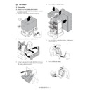
MX-5500N MX-6200N MX-7000N (serv.man72)
Installation Manual-Main Unit
Service Manual
|
20
|
5.46 MB
|
|
|
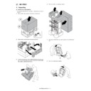
MX-5500N MX-6200N MX-7000N (serv.man73)
Configuration
Service Manual
|
2
|
538.55 KB
|
|
|
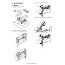
MX-5500N MX-6200N MX-7000N (serv.man74)
Cover Back cover-Installation Manual
Service Manual
|
4
|
1.06 MB
|
|
|
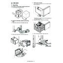
MX-5500N MX-6200N MX-7000N (serv.man75)
Whole Installation Manual
Service Manual
|
104
|
27.77 MB
|

|
MX-5500N MX-6200N MX-7000N
WHQL PCL6 32bit Printer Driver for 2k XP Vista Win7 server2003 200832 bit priNTer
Drivers
|
|
19.54 MB
|

|
MX-5500N MX-6200N MX-7000N (serv.man2)
WHQL 64bit Printer Driver for XP Vista Win7 server2003 200864 bit priNTer
Drivers
|
|
20.65 MB
|

|
MX-5500N MX-6200N MX-7000N (serv.man3)
Mac OS10.8 Driver Rquires Postscript option. Mac OS
Drivers
|
|
2.94 MB
|
|
|
MX-5500N MX-6200N MX-7000N (serv.man77)
Revised December 2011
Service Manual / Parts Guide
|
127
|
26.27 MB
|
|
|
MX-5500N MX-6200N MX-7000N (serv.man79)
Revised PWB Parts Guide.
Service Manual / Parts Guide
|
34
|
396.78 KB
|
|
|
MX-5500N MX-6200N MX-7000N (serv.man40)
Specification
Service Manual / Specification
|
16
|
314.08 KB
|
|
|
MX-5500N MX-6200N MX-7000N (serv.man92)
Parts change for productivity improvement.
Service Manual / Technical Bulletin
|
3
|
184.15 KB
|
|
|
MX-5500N MX-6200N MX-7000N (serv.man93)
Design change of MF Tray 2 Upper.
Service Manual / Technical Bulletin
|
2
|
216.35 KB
|
|
|
MX-5500N MX-6200N MX-7000N (serv.man94)
Change of Photo Sensor and Harness
Service Manual / Technical Bulletin
|
3
|
962.43 KB
|
|
|
MX-5500N MX-6200N MX-7000N (serv.man96)
CCE 1508 IMPROVEMENT OF PERFORMANCE WHEN OPENING CLOSING DSPF LOWER DOOR
Service Manual / Technical Bulletin
|
3
|
235.02 KB
|
|
|
MX-5500N MX-6200N MX-7000N (serv.man96)
CCE 1508 IMPROVEMENT OF PERFORMANCE WHEN OPENING CLOSING DSPF LOWER DOOR
Service Manual / Technical Bulletin
|
3
|
235.02 KB
|
|
|
MX-5500N MX-6200N MX-7000N (serv.man97)
Design change of delivery paper guide.
Service Manual / Technical Bulletin
|
2
|
91.45 KB
|
|
|
MX-5500N MX-6200N MX-7000N (serv.man97)
Design change of delivery paper guide.
Service Manual / Technical Bulletin
|
2
|
91.45 KB
|
|
|
MX-5500N MX-6200N MX-7000N (serv.man98)
CHANGE IN COLOUR OF PIPE CUSHION
Service Manual / Technical Bulletin
|
2
|
60.2 KB
|
|
|
MX-5500N MX-6200N MX-7000N (serv.man98)
CHANGE IN COLOUR OF PIPE CUSHION
Service Manual / Technical Bulletin
|
2
|
60.2 KB
|
|
|
MX-5500N MX-6200N MX-7000N (serv.man99)
Starting Powder List (This list takes priority over information in Service Manuals).
Service Manual / Technical Bulletin
|
4
|
66.25 KB
|
|
|
MX-5500N MX-6200N MX-7000N (serv.man99)
Starting Powder List (This list takes priority over information in Service Manuals).
Service Manual / Technical Bulletin
|
4
|
66.25 KB
|
|
|
MX-5500N MX-6200N MX-7000N (serv.man100)
Recommended shutdown procedure and Power Cycling of MFD
Service Manual / Technical Bulletin
|
1
|
186.43 KB
|
|
|
MX-5500N MX-6200N MX-7000N (serv.man100)
Recommended shutdown procedure and Power Cycling of MFD
Service Manual / Technical Bulletin
|
1
|
186.43 KB
|
|
|
MX-5500N MX-6200N MX-7000N (serv.man101)
IMPORTANT Handling of EEPROM's.
Service Manual / Technical Bulletin
|
5
|
203.32 KB
|
|
|
MX-5500N MX-6200N MX-7000N (serv.man102)
MODIFICATION OF NOISE GENERATED BY CONTACT BETWEEN TENSION PLATE AND DRIVE TRANSPORT FRAME.
Service Manual / Technical Bulletin
|
2
|
208.65 KB
|
|
|
MX-5500N MX-6200N MX-7000N (serv.man103)
CCE-1306 A REMINDER TO INSERT CONNECTORS TO DRIVER PWB COMPLETELY
Service Manual / Technical Bulletin
|
2
|
237.57 KB
|
|
|
MX-5500N MX-6200N MX-7000N (serv.man104)
IMPROVEMENT OF DETECTION ACCURACY FOR DSPF TRANSPORT UPPER ACTUATOR.
Service Manual / Technical Bulletin
|
2
|
198.78 KB
|
|
|
MX-5500N MX-6200N MX-7000N (serv.man105)
ENHANCEMENT TO PREVENT DETACHMENT OF PAPER FEED GUIDE TRANSPORT TOP ACTUATOR
Service Manual / Technical Bulletin
|
2
|
66.52 KB
|
|
|
MX-5500N MX-6200N MX-7000N (serv.man106)
CCE-1076 WHITE STREAK S DUE TO THE DOCTOR COVER SEAL OR INNER BLADE WEAR.
Service Manual / Technical Bulletin
|
3
|
280.8 KB
|
|
|
MX-5500N MX-6200N MX-7000N (serv.man107)
CCE-1067 Shape of the waste toner pipe D has been changed to improve operation.
Service Manual / Technical Bulletin
|
2
|
189.02 KB
|
|
|
MX-5500N MX-6200N MX-7000N (serv.man108)
CCE 950 COUNTERMESURE NOISE FROM DSPF UPPER AND LOWER TRANSPORT UNITS
Service Manual / Technical Bulletin
|
2
|
304.1 KB
|
|
|
MX-5500N MX-6200N MX-7000N (serv.man109)
FALSE DELIVERY PAPER FULL DETECTION DURING PAPER DELVERY.
Service Manual / Technical Bulletin
|
1
|
289.4 KB
|
|
|
MX-5500N MX-6200N MX-7000N (serv.man110)
F2-02 AND F2-64 ERROR CODE OCCURRING FROM EXCESSIVE LOAD ON THE TN ROLLER OF THE (BK) DV UNIT.
Service Manual / Technical Bulletin
|
2
|
150.3 KB
|
|
|
MX-5500N MX-6200N MX-7000N (serv.man111)
CCE-905 Noise from the lower HR bearing modification.
Service Manual / Technical Bulletin
|
2
|
342.83 KB
|
|
|
MX-5500N MX-6200N MX-7000N (serv.man112)
REF CCE837 ELIMINATING CHARGING IRREGULARITIES, IMPROVING CQ.
Service Manual / Technical Bulletin
|
2
|
366.93 KB
|
|
|
MX-5500N MX-6200N MX-7000N (serv.man113)
Ref CCE821 L4-04 OCCURRING FROM THE PEELING MG SIDE SHEET F OF THE DV UNIT (BK).
Service Manual / Technical Bulletin
|
1
|
30.24 KB
|
|
|
MX-5500N MX-6200N MX-7000N (serv.man114)
CCE817 MX-FNX4 ROM Upgrade 2. When paper is rolled over the folding roller, there has been cases where the paper has slipped.
Service Manual / Technical Bulletin
|
1
|
29.41 KB
|
|
|
MX-5500N MX-6200N MX-7000N (serv.man115)
CCE803 IMPROVEMENTS TO DUST RESISTANCE OF THE DSPF REDUCTION OPTICAL UNIT
Service Manual / Technical Bulletin
|
2
|
854.47 KB
|
|
|
MX-5500N MX-6200N MX-7000N (serv.man116)
REF CCE 794 2ND TRANSFER BELT BEAD STRENGTH INCREASED.
Service Manual / Technical Bulletin
|
2
|
470.85 KB
|
|
|
MX-5500N MX-6200N MX-7000N (serv.man117)
Ref CCE779 MX-CFX1 COUNTERMEASURES FOR JAM (HI_SEN_S, ETC.)RESULTING FROM MISALIGNED SPRING HOOK SECTION OF DELIVERY SENSOR LEVER.
Service Manual / Technical Bulletin
|
2
|
342.03 KB
|
|
|
MX-5500N MX-6200N MX-7000N (serv.man118)
Ref CCE773 MX-FN3 FN4 HOW TO REMOVE THE F1-37 ERROR WHEN REPLACING THE FINISHER PWB
Service Manual / Technical Bulletin
|
1
|
18.65 KB
|
|
|
MX-5500N MX-6200N MX-7000N (serv.man119)
Ref CCE788 E7-20 When printing in thick paper mode, FIRMWARE CHANGE.
Service Manual / Technical Bulletin
|
1
|
21.91 KB
|
|
|
MX-5500N MX-6200N MX-7000N (serv.man120)
CCE-744 MX-FRX3U DSK FIRMWARE ROM UPGRADE ICU VERSION 01.15.Dm Production Run Date December 2009
Service Manual / Technical Bulletin
|
5
|
43.47 KB
|
|
|
MX-5500N MX-6200N MX-7000N (serv.man121)
ARE-963 MX-LCX3N FIRMWARE UPGRADE V01.01. Production Run Date Febuary 2010
Service Manual / Technical Bulletin
|
2
|
28.95 KB
|
|
|
MX-5500N MX-6200N MX-7000N (serv.man122)
CCE770 COUNTERMEASURES AGAINST THE MIDDLE TRANSFER BELT BEAD DETERIORATION
Service Manual / Technical Bulletin
|
1
|
326.19 KB
|
|
|
MX-5500N MX-6200N MX-7000N (serv.man123)
CCE-768 LCD BACK LIGHT LAMP CHANGED
Service Manual / Technical Bulletin
|
1
|
27.14 KB
|
|
|
MX-5500N MX-6200N MX-7000N (serv.man124)
ARE-962 F1-46 TROUBLE CODE OCCURRENCE AFTER JAM PROCESSING.
Service Manual / Technical Bulletin
|
2
|
290.02 KB
|

|
MX-5500N MX-6200N MX-7000N (serv.man125)
REF ARE963 MX-LCX3N FIRMWARE UPGRADE.
Service Manual / Technical Bulletin
|
|
93.86 KB
|
|
|
MX-5500N MX-6200N MX-7000N (serv.man126)
CCE-752 COUNTERMEASURES TO PREVENT TRANSFER BELT SLIPPING DUE TO A COLLAR MISSING ON THE 1ST TRANSFER FOLLOWER ROLLER
Service Manual / Technical Bulletin
|
2
|
490.79 KB
|
|
|
MX-5500N MX-6200N MX-7000N (serv.man127)
CEE-750 PRECAUTIONS WHEN REPLACING THE WEB ROLLER
Service Manual / Technical Bulletin
|
2
|
617.5 KB
|
|
|
MX-5500N MX-6200N MX-7000N (serv.man128)
ARE-957 PREVENTION OF THE COOLING FAN MOTOR BEARING FIXING FROM BEING STRIPPED
Service Manual / Technical Bulletin
|
2
|
195.25 KB
|
|
|
MX-5500N MX-6200N MX-7000N (serv.man129)
ARE-958 PRECAUTIONS WHEN INSERTING A TONER CARTRIDGE
Service Manual / Technical Bulletin
|
1
|
15.47 KB
|
|
|
MX-5500N MX-6200N MX-7000N (serv.man130)
REF CCE722R POD1 JAM PROBLEM AND OTHERS, CAUSED BY TONER ADHERING TO POST-FUSING UPPER PG ON FUSING UNIT REVISED
Service Manual / Technical Bulletin
|
3
|
1.24 MB
|
|
|
MX-5500N MX-6200N MX-7000N (serv.man131)
REF CCE-730 PREVENTION OF THE DRUM SCUFFING AGAINST THE DV UNIT WHEN PULLED OUT
Service Manual / Technical Bulletin
|
2
|
768.82 KB
|
|
|
MX-5500N MX-6200N MX-7000N (serv.man132)
Operations Required for Machine Movement
Service Manual / Technical Bulletin
|
1
|
14.68 KB
|
|
|
MX-5500N MX-6200N MX-7000N (serv.man133)
CCE727 DAMAGE ON DRUM SURFACE CAUSED WHEN DV UNIT IS PULLED OUT.
Service Manual / Technical Bulletin
|
2
|
1.1 MB
|
|
|
MX-5500N MX-6200N MX-7000N (serv.man134)
ISSUING EXPLANATORY MATERIAL OF JOB LOG CODES.
Service Manual / Technical Bulletin
|
13
|
160.14 KB
|
|
|
MX-5500N MX-6200N MX-7000N (serv.man135)
REF. CCE-703 LFR CHANGES TO PERVENT SCRATCHES TO THE UFR.
Service Manual / Technical Bulletin
|
2
|
191.95 KB
|
|
|
MX-5500N MX-6200N MX-7000N (serv.man136)
CCE696 COUNTERMEASURES FOR ABNORMAL SOUND (PATTER)FROM BEARING SECTIONS OF UPPER AND LOWER HEAT ROLLERS OF FUSING UNIT.
Service Manual / Technical Bulletin
|
2
|
541.15 KB
|
|
|
MX-5500N MX-6200N MX-7000N (serv.man137)
CCE695 MX-FNX4 ROM UPGRADE ... (1).
Service Manual / Technical Bulletin
|
1
|
27.93 KB
|
|
|
MX-5500N MX-6200N MX-7000N (serv.man138)
CCE694 CHANGE OF INITIAL VALUES OF PREHEAT MODE AND AUTO POWER SHUT-OFF MODE INVOLVED IN SUPPORT OF ENERGY STAR VER1.1 (TIER II).
Service Manual / Technical Bulletin
|
1
|
22.91 KB
|
|
|
MX-5500N MX-6200N MX-7000N (serv.man139)
WEB IDLE GEAR MATERIAL CHANGED TO IMPROVE HEAT FRICTION RESISTANCE
Service Manual / Technical Bulletin
|
1
|
195.17 KB
|
|
|
MX-5500N MX-6200N MX-7000N (serv.man140)
CCE686 CHANGE OF SHAPE OF PROCESS F COVER.
Service Manual / Technical Bulletin
|
2
|
198.81 KB
|
|
|
MX-5500N MX-6200N MX-7000N (serv.man141)
CCE617 MODIFICATION TO FUSER UNIT, PREVENTING TONER ADHERTION TO UPPER HEAT ROLLER AND SEP PAWS
Service Manual / Technical Bulletin
|
4
|
1.65 MB
|
|
|
MX-5500N MX-6200N MX-7000N (serv.man142)
CCE591 COUNTERMEASURES FOR BK FOG.
Service Manual / Technical Bulletin
|
6
|
990.59 KB
|
|
|
MX-5500N MX-6200N MX-7000N (serv.man143)
MEASURE TO PREVENT WASTE TONER CLOGGING
Service Manual / Technical Bulletin
|
2
|
240.5 KB
|
|
|
MX-5500N MX-6200N MX-7000N (serv.man144)
IMPROVING HEAT- AND FRICTION-RESISTANCE MARGINS
Service Manual / Technical Bulletin
|
2
|
351.88 KB
|
|
|
MX-5500N MX-6200N MX-7000N (serv.man145)
PAPER FEED JAM (DPFD1_N4, ETC.) RESULTING FROM CONTACT BETWEEN SEPARATE CRIMPING SP OF CASSETTE PAPER FEED UNIT SECTION AND PF LOWER PG REINFORCE PLATE.
Service Manual / Technical Bulletin
|
2
|
282.83 KB
|
|
|
MX-5500N MX-6200N MX-7000N (serv.man146)
SOLUTION TO FAULT OF SLACKENED SCREWS SECURING OUTSIDE HL HOLDERS AND OUTSIDE HAENESS HOLDERS IN FUSING UNIT
Service Manual / Technical Bulletin
|
2
|
351.88 KB
|
|
|
MX-5500N MX-6200N MX-7000N (serv.man147)
COUNTERMEASURES FOR F2-40 TROUBLE RESULTING FROM LEAK IN MC UNIT SECTION.
Service Manual / Technical Bulletin
|
2
|
85.83 KB
|
|
|
MX-5500N MX-6200N MX-7000N (serv.man148)
POINTS TO KEEP IN MIND WHEN ADJUSTING
Service Manual / Technical Bulletin
|
1
|
22.07 KB
|
|
|
MX-5500N MX-6200N MX-7000N (serv.man149)
REINFORCEMENT OF DSPF GUIDES.
Service Manual / Technical Bulletin
|
2
|
75.83 KB
|
|
|
MX-5500N MX-6200N MX-7000N (serv.man150)
COMPATIBILITY OF LWR THERMOSTAT PART CHANGE.
Service Manual / Technical Bulletin
|
2
|
56.51 KB
|
|
|
MX-5500N MX-6200N MX-7000N (serv.man151)
REMEDY FOR MARKS IN REVERSE OF PAPER WHEN DOUBLE SIDING
Service Manual / Technical Bulletin
|
2
|
130.22 KB
|
|
|
MX-5500N MX-6200N MX-7000N (serv.man152)
PROCEDURE FOR REPLACING MFP PWB
Service Manual / Technical Bulletin
|
2
|
206.24 KB
|
|
|
MX-5500N MX-6200N MX-7000N (serv.man153)
COUNTERMEASURE TO IMPROVE UNEVEN SHADING OF IMAGE.
Service Manual / Technical Bulletin
|
1
|
31.16 KB
|
|
|
MX-5500N MX-6200N MX-7000N (serv.man154)
REDUCING UNEVEN CHARGE(IMAGE STREAKING)IMPROVEMENT OF MC UNIT CLEANING PERFORMANCE.
Service Manual / Technical Bulletin
|
2
|
48.71 KB
|
|
|
MX-5500N MX-6200N MX-7000N (serv.man155)
MX 55-7000 DRIVE UNIT CHANGES FOR BLACK DRUM DRIVE MXFNX3 4 RETURN ROLLER SHAFT PARTS CHANGES
Service Manual / Technical Bulletin
|
2
|
169.32 KB
|
|
|
MX-5500N MX-6200N MX-7000N (serv.man156)
COUNTERMEASURE FOR TRANSFER MISALIGNMENT 95MM FROM LEAD EDGE OF PAPER
Service Manual / Technical Bulletin
|
2
|
73.13 KB
|
|
|
MX-5500N MX-6200N MX-7000N (serv.man157)
PREVENTION OF TONER BOTTLE COUPLING DISENGAGEMENT.
Service Manual / Technical Bulletin
|
2
|
68.86 KB
|
|
|
MX-5500N MX-6200N MX-7000N (serv.man158)
RELEASE OF MXFNX1 3 4 STAPLE UNIT COMPLETE.
Service Manual / Technical Bulletin
|
1
|
65.53 KB
|
|
|
MX-5500N MX-6200N MX-7000N (serv.man159)
CCE 545- MX FNX3 4 CHANGES TO TIMING BELT MYLAR.
Service Manual / Technical Bulletin
|
2
|
85.08 KB
|
|
|
MX-5500N MX-6200N MX-7000N (serv.man160)
CCE 541- MX CFX1 ROM CHANGE BULLETIN ONLY TO COUNTERACT HI_SEN STATUS (A02 0103D0)
Service Manual / Technical Bulletin
|
1
|
59.02 KB
|
|
|
MX-5500N MX-6200N MX-7000N (serv.man161)
CCE 534- L4-35 DUE TO ELECTRICAL NOISE FROM DELIVERY MOTOR.
Service Manual / Technical Bulletin
|
3
|
101.03 KB
|
|
|
MX-5500N MX-6200N MX-7000N (serv.man162)
CCE 528- PREVENTION OF FUSER NOISE.
Service Manual / Technical Bulletin
|
2
|
66.69 KB
|
|
|
MX-5500N MX-6200N MX-7000N (serv.man163)
CCE 519- PREVENTION OF DAMAGE TO AC-DC HARNESS COATING.
Service Manual / Technical Bulletin
|
2
|
85.66 KB
|
|
|
MX-5500N MX-6200N MX-7000N (serv.man164)
CCE 524- LSU HEATER PARTS AVAILABLE AS SERVICE PARTS.
Service Manual / Technical Bulletin
|
5
|
251.27 KB
|
|
|
MX-5500N MX-6200N MX-7000N (serv.man165)
CCE 515- IMPROVEMENT IN WASTE TONER SCATTER FROM WASTE TONER SHUTTER.
Service Manual / Technical Bulletin
|
2
|
79 KB
|
|
|
MX-5500N MX-6200N MX-7000N (serv.man166)
CCE 514- IMPROVEMENT TO DEV GEAR PITCH TO COUNTERACT BANDING.
Service Manual / Technical Bulletin
|
2
|
67.55 KB
|
|
|
MX-5500N MX-6200N MX-7000N (serv.man167)
CCE 511-STRENGTH IMPROVEMENT OF CASSETTE LIFT MOTOR A.
Service Manual / Technical Bulletin
|
2
|
81.85 KB
|
|
|
MX-5500N MX-6200N MX-7000N (serv.man168)
CCE 510- INFORMATION OF PARTS CHANGE TO FUSER ASSEMBLY
Service Manual / Technical Bulletin
|
2
|
91.87 KB
|
|
|
MX-5500N MX-6200N MX-7000N (serv.man169)
PME 487-PARTS CHANGE TO MX LCX2 LCC
Service Manual / Technical Bulletin
|
1
|
43.3 KB
|
|
|
MX-5500N MX-6200N MX-7000N (serv.man170)
CCE 508- REDUCTION OF WEB OIL TO IMPROVE PAPER SEPERATION FROM UFR
Service Manual / Technical Bulletin
|
1
|
65.21 KB
|
|
|
MX-5500N MX-6200N MX-7000N (serv.man171)
CCE 489-NEW SET OF SERVICE PARTS THAT COMBINES THE FILTER COVER WITH TONER FILTER.
Service Manual / Technical Bulletin
|
1
|
64.73 KB
|
|
|
MX-5500N MX-6200N MX-7000N (serv.man172)
CCE 499-PRIMARY TRANSFER CHARGE ROLLER PARTS CHANGE TO IMPROVE PRODUCTIVITY
Service Manual / Technical Bulletin
|
1
|
73.71 KB
|
|
|
MX-5500N MX-6200N MX-7000N (serv.man173)
DV COVER MOUNTING INSTRUCTIONS TO PREVENT DAMAGE
Service Manual / Technical Bulletin
|
2
|
98.61 KB
|
|
|
MX-5500N MX-6200N MX-7000N (serv.man174)
NEW SET OF SERVICE PARTS THAT COMBINES THE FILTER COVER WITH TONER FILTER.
Service Manual / Technical Bulletin
|
1
|
59.68 KB
|
|
|
MX-5500N MX-6200N MX-7000N (serv.man175)
CONTACT PREVENTION BETWEEN THE LOWER MAIN HARNESS AND THE CENTRAL VENTILATION FAN MOTOR INSIDE THE MACHINE.
Service Manual / Technical Bulletin
|
2
|
94.05 KB
|
|
|
MX-5500N MX-6200N MX-7000N (serv.man176)
IMPROVED ACCESS TO TANDEM TRAYS 1 2 WHEN REPLENISHING PAPER
Service Manual / Technical Bulletin
|
7
|
309.05 KB
|
|
|
MX-5500N MX-6200N MX-7000N (serv.man177)
STRENGTHENED FUSER FRONT COVER
Service Manual / Technical Bulletin
|
2
|
73.86 KB
|
|
|
MX-5500N MX-6200N MX-7000N (serv.man178)
IMPROVED PACKING TO PREVENT SLIT GLASS BREAKAGE
Service Manual / Technical Bulletin
|
2
|
80.07 KB
|
|
|
MX-5500N MX-6200N MX-7000N (serv.man179)
IMPROVEMENT OF CONTACT AREA OF THERMISTOR TO FUSER ROLLER
Service Manual / Technical Bulletin
|
2
|
88.22 KB
|
|
|
MX-5500N MX-6200N MX-7000N (serv.man180)
STRENGHTHENING OF MF TRAY HARNESS
Service Manual / Technical Bulletin
|
2
|
79.49 KB
|
|
|
MX-5500N MX-6200N MX-7000N (serv.man181)
SCORE LINES ON COPIES FROM DELIVERY ROLLERS
Service Manual / Technical Bulletin
|
2
|
69.65 KB
|
|
|
MX-5500N MX-6200N MX-7000N (serv.man182)
CCE 434-PAPER FEEDS IN A BUNDLE OWING TO THE STOPPER THAT DESCENDS WHEN LOADING PAPER TO THE BYPASS TRAY.
Service Manual / Technical Bulletin
|
2
|
78.31 KB
|
|
|
MX-5500N MX-6200N MX-7000N (serv.man183)
BARRIETA GREASE SPRAY FOR FUSING UNIT
Service Manual / Technical Bulletin
|
2
|
77.64 KB
|
|
|
MX-5500N MX-6200N MX-7000N (serv.man184)
MXFNX3 4 PARTS CHANGE-STAPLE UNIT,COVERS HANDLE
Service Manual / Technical Bulletin
|
1
|
46.98 KB
|
|
|
MX-5500N MX-6200N MX-7000N (serv.man185)
CCE 448 MX FNX3 4 JAM (FED_S) CAUSED BY ENTRANCE SENSOR LEVER STICKING HOLDER.
Service Manual / Technical Bulletin
|
1
|
65.16 KB
|
|
|
MX-5500N MX-6200N MX-7000N (serv.man186)
PARTS CHANGE MAIN CHARGE COVER WASTE TONER PANEL
Service Manual / Technical Bulletin
|
2
|
82.89 KB
|
|
|
MX-5500N MX-6200N MX-7000N (serv.man187)
CCE 424-H4 02 DAMAGED SUB HEATER LAMP (200V)
Service Manual / Technical Bulletin
|
1
|
77.73 KB
|
|
|
MX-5500N MX-6200N MX-7000N (serv.man188)
CCE 395-LOCK PREVENTION OF SHAFT-WASTE TONER TRANSPORT SECTION
Service Manual / Technical Bulletin
|
2
|
87.03 KB
|
|
|
MX-5500N MX-6200N MX-7000N (serv.man189)
CCE 408-MX IMPROVEMENT OF THERMOSTAT OFF TEMPERATURE-FUSER UNIT
Service Manual / Technical Bulletin
|
1
|
78.36 KB
|
|
|
MX-5500N MX-6200N MX-7000N (serv.man190)
CCE 401- MXCFX1 IMPROVEMENT IN SENSOR LEVER TO ELIMINATE HI_SEN MISFEED
Service Manual / Technical Bulletin
|
1
|
63.91 KB
|
|
|
MX-5500N MX-6200N MX-7000N (serv.man191)
CCE 392- MX FNX3 4 PAPER DETECTION FLAG ERRORS OUTPUT TRAY SYNCHRONISATION FAULT
Service Manual / Technical Bulletin
|
2
|
80.52 KB
|
|
|
MX-5500N MX-6200N MX-7000N (serv.man192)
CCE 340-MX CFX1 INSERTER ROM UPGRADE
Service Manual / Technical Bulletin
|
1
|
62.58 KB
|
|
|
MX-5500N MX-6200N MX-7000N (serv.man193)
CCE 335-CHANGE OF FULL WEIGHT OF WASTE TONER BOTTLE
Service Manual / Technical Bulletin
|
2
|
85.42 KB
|
|
|
MX-5500N MX-6200N MX-7000N (serv.man194)
CCE 324-NOTE ON MX-FXX1 INSTALLATION
Service Manual / Technical Bulletin
|
1
|
67.95 KB
|
|
|
MX-5500N MX-6200N MX-7000N (serv.man195)
GENERAL PROCEDURE FOR COLOUR CALIBRATION SET-UP
Service Manual / Technical Bulletin
|
2
|
83.06 KB
|
|
|
MX-5500N MX-6200N MX-7000N (serv.man196)
CCE 301-CAUTIONS ON HDD REPLACEMENT AND PROCEDURE FOR UPDATING INSTRUCTION MANUAL.
Service Manual / Technical Bulletin
|
5
|
135.85 KB
|
|
|
MX-5500N MX-6200N MX-7000N (serv.man197)
CCE 380-IMPROVEMENT IN CLEANING BY PREVENTING THE DEFORMATION OF THE TONER STIRRING SHEET OF THE PROCESS UNIT.
Service Manual / Technical Bulletin
|
2
|
118.15 KB
|
|
|
MX-5500N MX-6200N MX-7000N (serv.man198)
MX PNX2A-D ADJUSTMENTS AFTER REPLACING HOLE PUNCH UNIT CONTROL PCB PREVENTING F1-38 ERROR
Service Manual / Technical Bulletin
|
2
|
107.61 KB
|
|
|
MX-5500N MX-6200N MX-7000N (serv.man199)
CCE 417-JAM OWING TO DEFECTIVE RETURN OF RIGHT HAND PAPER DISCHARGING GATE
Service Manual / Technical Bulletin
|
1
|
68.79 KB
|
|
|
MX-5500N MX-6200N MX-7000N (serv.man200)
CHANGES TO TRANSFER HVT PCB
Service Manual / Technical Bulletin
|
2
|
112.31 KB
|
|
|
MX-5500N MX-6200N MX-7000N (serv.man201)
MX PNX2A-D ROM UPGRADE(CONTROL No A01 VERSION 0103DO) WITH FIRMWARE PCU 0104DO 0105DO
Service Manual / Technical Bulletin
|
1
|
59.7 KB
|
|
|
MX-5500N MX-6200N MX-7000N (serv.man202)
MX FNX3 4 ROM UPGRADE(CONTROL No A02 FINISHER VERSION 0103DO)WITH PCU 01.04.DO 01.05.DO
Service Manual / Technical Bulletin
|
1
|
59.7 KB
|
|
|
MX-5500N MX-6200N MX-7000N (serv.man203)
REVISED TEMP TABLE ADJUSTMENTS FOR PCU 01.04 AND PCU 01.05
Service Manual / Technical Bulletin
|
3
|
328.84 KB
|

|
MX-5500N MX-6200N MX-7000N (serv.man204)
FIRMWARE FOR MX5500 6200 ONLY TO OVERCOME FUSER OFFSET (PCU 01.04.0D)
Service Manual / Technical Bulletin
|
|
27.66 MB
|
|
|
MX-5500N MX-6200N MX-7000N (serv.man205)
Adjustment to system settings to overcome fusing offset
Service Manual / Technical Bulletin
|
2
|
46.04 KB
|
|
|
MX-5500N MX-6200N MX-7000N (serv.man206)
CCE 414- CORRECTION OF FUSER OFFSET PROBLEMS MX 7000 ONLY SEE UPDATES PCU 01.05.0D
Service Manual / Technical Bulletin
|
2
|
329.56 KB
|
|
|
MX-5500N MX-6200N MX-7000N (serv.man207)
SCANNER DRYING HEATER AS SERVICE PART
Service Manual / Technical Bulletin
|
5
|
244.94 KB
|
|
|
MX-5500N MX-6200N MX-7000N (serv.man208)
CCE 419- MXFNX3 FNX4 PARTS CORRECTION
Service Manual / Technical Bulletin
|
1
|
63.49 KB
|
|
|
MX-5500N MX-6200N MX-7000N (serv.man209)
SERV PARTS SETTING OF MAIN UNIT CASSETTE TANDEM HEATER
Service Manual / Technical Bulletin
|
12
|
517.94 KB
|
|
|
MX-5500N MX-6200N MX-7000N (serv.man210)
SERVICE PARTS OF ELECTRICAL HEATER COMPONENTS
Service Manual / Technical Bulletin
|
7
|
2.28 MB
|
|
|
MX-5500N MX-6200N MX-7000N (serv.man211)
CCE 371-REMINDER TO UNLOCK PAPER CASSETTE
Service Manual / Technical Bulletin
|
2
|
80.67 KB
|
|
|
MX-5500N MX-6200N MX-7000N (serv.man212)
IC Failure causing scan copy issues
Service Manual / Technical Bulletin
|
4
|
116.08 KB
|
|
|
MX-5500N MX-6200N MX-7000N (serv.man213)
CCE 360-COLOUR TONER NEAR END 26-69 IMPROVEMENT OF TONER SCATTER 44-4,61-3.
Service Manual / Technical Bulletin
|
1
|
60.05 KB
|
|
|
MX-5500N MX-6200N MX-7000N (serv.man214)
CCE 331- SETTING OF DSPF DEDICATED CHART
Service Manual / Technical Bulletin
|
2
|
113.85 KB
|

|
MX-5500N MX-6200N MX-7000N (serv.man86)
SAP Device Types for MX Colour devices.
Driver / Update
|
|
3.18 MB
|

|
MX-5500N MX-6200N MX-7000N (serv.man87)
ROM control No.A15 ROM Version 0103D0 SEE BULLETIN CCE817
Driver / Update
|
|
150.09 KB
|

|
MX-5500N MX-6200N MX-7000N (serv.man88)
ROM control No.C02 ICU 01.15.D0,PCU 01.11.D0 1. SEE BULLETIN CCE788
Driver / Update
|
|
27.86 MB
|

|
MX-5500N MX-6200N MX-7000N (serv.man89)
PPD2_PRI Jam When Using Citrix Universal Printer
Driver / Update
|
|
6.41 MB
|

|
MX-5500N MX-6200N MX-7000N (serv.man90)
PPD2_PRI Jam When Using Citrix Universal Printer
Driver / Update
|
|
6.12 MB
|

|
MX-5500N MX-6200N MX-7000N (serv.man91)
Safecom Special Firmware PCU Version 01.14.D0b0
Driver / Update
|
|
27.85 MB
|
|
|
MX-5500N MX-6200N MX-7000N (serv.man4)
GENERAL PROCEDURE FOR COLOUR CALIBRATION SET-UP
Handy Guide
|
2
|
83.06 KB
|
|
|
MX-5500N MX-6200N MX-7000N (serv.man5)
VERSION 1A
Handy Guide
|
54
|
1.04 MB
|
|
|
MX-5500N MX-6200N MX-7000N (serv.man6)
HANDYGUIDE VERSION 1.1
Handy Guide
|
52
|
942.82 KB
|
|
|
MX-5500N MX-6200N MX-7000N (serv.man80)
How To Read A Main Machine Serial Number
FAQ
|
1
|
16.5 KB
|

|
MX-5500N MX-6200N MX-7000N (serv.man81)
UPDATED PJL PCL PS Command Lists
FAQ
|
|
128.84 KB
|

|
MX-5500N MX-6200N MX-7000N (serv.man82)
Firmware Combi_0112D0c0_B RIPFIX
FAQ
|
|
27.89 MB
|

|
MX-5500N MX-6200N MX-7000N (serv.man83)
0112 F w version B11 DEC07
FAQ
|
|
27.96 MB
|
|
|
MX-5500N MX-6200N MX-7000N (serv.man84)
How to connect MX colour product to Linux UNIX systems using CUPS
FAQ
|
9
|
1.45 MB
|

|
MX-5500N MX-6200N MX-7000N (serv.man85)
PCL PJL COMMANDS FOR MX SERIES
FAQ
|
|
69.87 KB
|
|
|
MX-5500N MX-6200N MX-7000N (serv.man215)
MAGENTA DEV
Regulatory Data
|
4
|
32.74 KB
|
|
|
MX-5500N MX-6200N MX-7000N (serv.man216)
YELLOW TONER
Regulatory Data
|
4
|
32.34 KB
|
|
|
MX-5500N MX-6200N MX-7000N (serv.man217)
YELLOW DEV
Regulatory Data
|
4
|
32 KB
|
|
|
MX-5500N MX-6200N MX-7000N (serv.man218)
CYAN DEV
Regulatory Data
|
4
|
32.73 KB
|
|
|
MX-5500N MX-6200N MX-7000N (serv.man219)
BLACK DEV
Regulatory Data
|
4
|
34.84 KB
|
|
|
MX-5500N MX-6200N MX-7000N (serv.man220)
MAGENTA TONER
Regulatory Data
|
4
|
32.33 KB
|
|
|
MX-5500N MX-6200N MX-7000N (serv.man221)
CYAN TONER
Regulatory Data
|
4
|
32.31 KB
|
|
|
MX-5500N MX-6200N MX-7000N (serv.man222)
BLACK TONER
Regulatory Data
|
4
|
34.43 KB
|
|
|
MX-5500N MX-6200N MX-7000N (serv.man7)
Updated December 2011
Peripheral
|
17
|
1.41 MB
|
|
|
MX-5500N MX-6200N MX-7000N (serv.man8)
Updated Jan 08
Peripheral
|
20
|
2.34 MB
|
|
|
MX-5500N MX-6200N MX-7000N (serv.man9)
FULL CIRCUIT DIAGRAM 55 62 7000 LCX2 3 FNX3 4 PNX2A-D RBX2 CFX1 FXX1
Peripheral
|
127
|
21.31 MB
|
|
|
MX-5500N MX-6200N MX-7000N (serv.man10)
MX-LCX2 SERVICE MANUAL COMPLETE
Peripheral
|
30
|
2.2 MB
|
|
|
MX-5500N MX-6200N MX-7000N (serv.man11)
MX-LCX3 SERVICE MANUAL COMPLETE
Peripheral
|
34
|
3.59 MB
|
|
|
MX-5500N MX-6200N MX-7000N (serv.man12)
MX- PEX2 PARTS GUIDE
Peripheral
|
8
|
475.38 KB
|
|
|
MX-5500N MX-6200N MX-7000N (serv.man13)
WHOLE PARTS GUIDE MXFNX3 4 MXPNX2-4 MXRBX2
Peripheral
|
76
|
8.86 MB
|
|
|
MX-5500N MX-6200N MX-7000N (serv.man14)
MX-FNX3 4 MX-RBX2 MXPNX2A-D SERVICE MANUAL-Product Outline
Peripheral
|
2
|
339.95 KB
|
|
|
MX-5500N MX-6200N MX-7000N (serv.man15)
MX-FNX3 4 MX-RBX2 MXPNX2A-D SERVICE MANUAL-Specifications
Peripheral
|
3
|
117.74 KB
|
|
|
MX-5500N MX-6200N MX-7000N (serv.man16)
MX-FNX3 4 MX-RBX2 MXPNX2A-D SERVICE MANUAL-External Views Internal Structures
Peripheral
|
8
|
610.96 KB
|
|
|
MX-5500N MX-6200N MX-7000N (serv.man17)
MX-FNX3 4 MX-RBX2 MXPNX2A-D SERVICE MANUAL-Operational Description
Peripheral
|
28
|
3.26 MB
|
|
|
MX-5500N MX-6200N MX-7000N (serv.man18)
MX-FNX3 4 MX-RBX2 MXPNX2A-D SERVICE MANUAL-Disassembly Assembly-1
Peripheral
|
39
|
12.88 MB
|
|
|
MX-5500N MX-6200N MX-7000N (serv.man19)
MX-FNX3 4 MX-RBX2 MXPNX2A-D SERVICE MANUAL-Disassembly Assembly-2
Peripheral
|
30
|
11.13 MB
|
|
|
MX-5500N MX-6200N MX-7000N (serv.man20)
MX-FNX3 4 MX-RBX2 MXPNX2A-D SERVICE MANUAL-Maintenance
Peripheral
|
1
|
232.79 KB
|
|
|
MX-5500N MX-6200N MX-7000N (serv.man21)
MX-FNX3 4 MX-RBX2 MX-PNX2A-D SERVICE MANUAL-Adjustments
Peripheral
|
4
|
195.33 KB
|
|
|
MX-5500N MX-6200N MX-7000N (serv.man22)
MX-FNX3 4 MX-RBX2 MX-PNX2A-D SERVICE MANUAL-Self Diag Message Trouble code
Peripheral
|
4
|
102.18 KB
|
|
|
MX-5500N MX-6200N MX-7000N (serv.man23)
MX-FNX3 4 MX-RBX2 MX-PNX2A-D SERVICE MANUAL-Electrical Section
Peripheral
|
13
|
541.47 KB
|
|
|
MX-5500N MX-6200N MX-7000N (serv.man24)
MX CFX1 SERVICE MANUAL COMPLETE
Peripheral
|
39
|
4.64 MB
|
|
|
MX-5500N MX-6200N MX-7000N (serv.man25)
MX- PEX2 SERVICE MANUAL
Peripheral
|
99
|
2.87 MB
|
|
|
MX-5500N MX-6200N MX-7000N (serv.man26)
MX PEX2 INSTALLATION MANUAL
Peripheral
|
12
|
2.19 MB
|
|
|
MX-5500N MX-6200N MX-7000N (serv.man27)
MX-RBX2 Paper Pass Unit-Installation Manual
Peripheral
|
5
|
2.18 MB
|
|
|
MX-5500N MX-6200N MX-7000N (serv.man28)
MX-FNX3 4K Finisher-Installation Manual
Peripheral
|
8
|
2.55 MB
|
|
|
MX-5500N MX-6200N MX-7000N (serv.man29)
MX-FNX4 4K Saddle Stitch Finisher-Installation Manual
Peripheral
|
9
|
3.08 MB
|
|
|
MX-5500N MX-6200N MX-7000N (serv.man30)
MX-PNX2A-D Punch Module-Installation Manual
Peripheral
|
6
|
2.09 MB
|
|
|
MX-5500N MX-6200N MX-7000N (serv.man31)
MX-CFX1 Inserter-Installation Manual
Peripheral
|
10
|
3.06 MB
|
|
|
MX-5500N MX-6200N MX-7000N (serv.man33)
MX-LCX3 LCT A3-Installation Manual
Peripheral
|
13
|
3.72 MB
|
|
|
MX-5500N MX-6200N MX-7000N (serv.man34)
MX-PKX1 PS3 Expansion Kit-Installation Manual
Peripheral
|
1
|
90.1 KB
|
|
|
MX-5500N MX-6200N MX-7000N (serv.man35)
MX-FRX3 FRX3U Data security Kit-Installation Manual
Peripheral
|
5
|
1.03 MB
|
|
|
MX-5500N MX-6200N MX-7000N (serv.man36)
MX-FXX1-Fax Expansion Kit-Installation Manual
Peripheral
|
6
|
1.07 MB
|
|
|
MX-5500N MX-6200N MX-7000N (serv.man37)
AR-PF1-Barcode Font kit-Installation Manual
Peripheral
|
4
|
920.53 KB
|
|
|
MX-5500N MX-6200N MX-7000N (serv.man38)
MX-FWX1-Internet Expansion kit-Installation Manual
Peripheral
|
1
|
87.18 KB
|
|
|
MX-5500N MX-6200N MX-7000N (serv.man39)
MX-AMX1 Application INtergration module-Installation Manual
Peripheral
|
1
|
84.72 KB
|


