Sharp MX-5500N / MX-6200N / MX-7000N (serv.man21) Peripheral ▷ View online
MX-FNX4 ADJUSTMENTS 8 – 1
MX-FNX4
Service Manual
[8] ADJUSTMENTS
1. Finisher, saddle stitcher section
A. Basic adjustments
(1) Upper curl mode
a. Outline
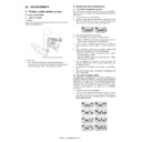
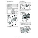
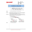
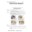
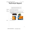
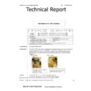
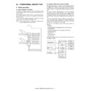
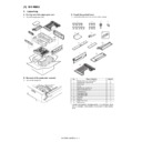
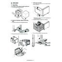
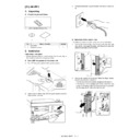
Paper may not be stacked properly depending on the paper state.
(Refer to the figure below.)
Paper may not be stacked properly depending on the paper state.
(Refer to the figure below.)
In such a case:
1) Turn back and set the paper in the paper feed cassette.
1) Turn back and set the paper in the paper feed cassette.
If the upper curl is greater than that before resetting the paper,
turn back the paper again to set in the previous state.
turn back the paper again to set in the previous state.
B. Adjustments when replacing parts
(1) Adjustment of alignment position
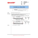
This adjustment is required when the finisher controller PCB is
replaced or when it is required to change the alignment position for
some reason.
1)
replaced or when it is required to change the alignment position for
some reason.
1)
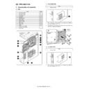
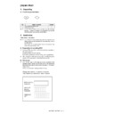
Remove the rear cover in the finisher.
2)
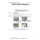
Check to confirm that the power of the host machine is turned
OFF, and set SW104 on the finisher controller PCB as shown
below, according to the paper used for the adjustment.
OFF, and set SW104 on the finisher controller PCB as shown
below, according to the paper used for the adjustment.
3)
Turn ON the power of the host machine.
4)
Press the SW103 on the finisher controller PCB once.
* When the SW103 is pressed, the swing guide is opened to
* When the SW103 is pressed, the swing guide is opened to
shift the alignment plates to the specified position.
5)
Insert ten sheets of A4/LTR paper between the alignment
plates, and push the paper so that it is in contact with the stop-
per.
plates, and push the paper so that it is in contact with the stop-
per.
6)
Press the SW101 or SW102 on the finisher controller PCB
until the alignment plates come in contact with paper.
* When the SW101 is pressed, the alignment plate is shifted
until the alignment plates come in contact with paper.
* When the SW101 is pressed, the alignment plate is shifted
to the front side by 0.42mm.
* When the SW102 is pressed, the alignment plate is shifted
to the rear side by 0.42mm.
7)
After the adjustment is completed, remove the paper, and
press the SW103 on the finisher controller PCB once to save
the adjustment value.
press the SW103 on the finisher controller PCB once to save
the adjustment value.
8)
Set all the bits of the SW104 on the finisher controller PCB to
OFF.
OFF.
9)
Turn OFF the power of the host machine, and install the rear
cover of the finisher.
cover of the finisher.
(2) Adjustment of staple position
This adjustment is performed when the finisher controller PCB is
replaced or when it is required to change the staple position for
some reason. If the paper used for the adjustment is of AB series,
front/back stapling adjustments are performed for A4/A4R, respec-
tively. When the paper used for the adjustment is of inch series,
front/back binding adjustments are performed for LTR/LTRR,
respectively.
1)
Remove the rear cover of the finisher.
2)
Check to confirm that the power of the host machine is turned
OFF, and set the SW104 on the finisher controller PCB as
shown below, according to the paper used for the adjustment
and the stapling position.
OFF, and set the SW104 on the finisher controller PCB as
shown below, according to the paper used for the adjustment
and the stapling position.
When A4 is used
When LTR is used
A4/staple in the front
A4R/staple in the front
LTR/staple in the front
LTRR/staple in the front
A4/staple at the back
A4R/staple at the back
LTR/staple at the back
LTRR/staple at the back
MX-FNX4 ADJUSTMENTS 8 – 2
3) Turn ON the power of the host machine.
4) Press the SW103 on the finisher controller PCB once.
4) Press the SW103 on the finisher controller PCB once.
* When SW103 is pressed, the swing guide is opened, and
the alignment plates are shifted to the specified positions.
5) Insert a sheet between the alignment plates, and push it so
that it is in contact with the stopper. Push the paper so that the
rear edge is in contact with the rear alignment plate.
* If there is a clearance of 1mm or more between the front
rear edge is in contact with the rear alignment plate.
* If there is a clearance of 1mm or more between the front
alignment plate and the front edge of paper, stop the adjust-
ment of staple position, and adjust the alignment position.
Then, perform adjustment of the staple position again.
ment of staple position, and adjust the alignment position.
Then, perform adjustment of the staple position again.
6) Press the SW103 on the finisher controller PCB once to per-
form stapling. Since, however, paper is not discharged, the
stapled paper must be manually removed and the stapling
position must be checked.
stapled paper must be manually removed and the stapling
position must be checked.
7) Press the SW103 on the finisher controller PCB once.
8) If the stapling position is proper, insert a sheet of paper
8) If the stapling position is proper, insert a sheet of paper
between the alignment plates, and push it so that it is in con-
tact with the stopper. Push the paper so that the rear edge is in
contact with the rear alignment plate. Press the SW103 once
(stapling/adjustment value saving), and go to the step 11).
tact with the stopper. Push the paper so that the rear edge is in
contact with the rear alignment plate. Press the SW103 once
(stapling/adjustment value saving), and go to the step 11).
9) To adjust the stapling position, press the SW101 or SW102 on
the finisher controller PCB.
* When the SW101 is pressed, the stapling position is shifted
* When the SW101 is pressed, the stapling position is shifted
to the front side by 0.49mm.
* When the SW102 is pressed, the stapling position is shifted
to the rear side by 0.49mm.
10) Repeat the steps 5) and 6) to check that the stapling position is
properly adjusted.
11) Set all the bits of the SW104 on the finisher controller PCB to
OFF.
12) Turn OFF the power of the host machine, and install the rear
cover of the finisher.
(3) Adjustment of folding position (MX-FNX4)
To adjust the folding position, change the setting of bits from 6 to 8
of the DIPSW1 on the saddle stitcher controller PCB, and adjust
the folding position to the stitch position. (Adjust the paper position-
ing plate shift amount from the stitch position to the folding posi-
tion.)
If the saddle stitcher controller PCB is replaced, shift the setting of
the DIPSW1 on the old PCB to the new PCB. If the folding position
must be changed for some reason, this adjustment should be per-
formed.
1) Check to confirm that the power of the host machine is turned
OFF, and separate the finisher from the host machine. If the
optional punch module is installed, remove it from the finisher.
optional punch module is installed, remove it from the finisher.
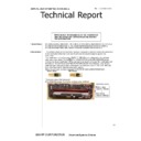
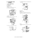
2) Remove the PCB cover, and set the bits from 1 to 4 of the
SW504 on the saddle stitcher controller PCB as shown below:
3) Remove the rear cover, and open the inlet cover of the saddle
stitcher. Then, fix the inlet cover sensor (FSINDD) and the inlet
door switch (FSINDSW) actuator with tape.
door switch (FSINDSW) actuator with tape.
4)
Put a mark on the top of the paper before paper feeding. Use
two sheets of A3 or LDR paper.
two sheets of A3 or LDR paper.
5)
Turn ON the power of the host machine.
6)
Press the SW1 of the saddle stitcher controller PCB. (When
LDR is used, keep pressing for 3 sec or more.) Then, the feed
motor (FSFM) starts running.
LDR is used, keep pressing for 3 sec or more.) Then, the feed
motor (FSFM) starts running.
7)
Feed two sheets of paper from the saddle inlet cover section.
Feed paper until the paper lead edge is in contact with the
paper positioning plate.
Feed paper until the paper lead edge is in contact with the
paper positioning plate.
8)
Close the inlet cover.
9)
Press the SW1 of the saddle stitcher controller PCB.
* The saddle stitcher section stitches, folds, and discharges
* The saddle stitcher section stitches, folds, and discharges
paper automatically,
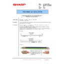
10) Measure the distance (L) between the stitch position and the
folding position. There are a "positive adjustment width" and a
"negative adjustment width" depending on the relations of the
stitch position and the folding position.
* If the stitch position is lower than the folding position, the
"negative adjustment width" depending on the relations of the
stitch position and the folding position.
* If the stitch position is lower than the folding position, the
width is the "positive adjustment width."
* If the stitch position is higher than the folding position, the
width is the "negative adjustment width."
Do not change the
setting of bits from 5 to 8.
Mark
A3/LDR paper
Paper feed direction
Mark
Example of a positive
adjustment value
Unit: mm
Ex.) If L is 1mm, the width is "+1mm".
Folding position
Example of a negative
adjustment value
Mark
Stitch position
Folding position
Stitch position
Unit: mm
Ex.) If L is 0.5mm, the width is "-0.5mm".
MX-FNX4 ADJUSTMENTS 8 – 3
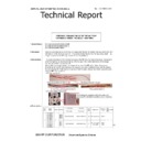
11) Change the setting of bits from 6 to 8 of the SW504 depending
on the clearance. Refer to the table below.
* When the adjustment width is 0:
* When the adjustment width is 0:
Since the stitch position is aligned with the folding position,
the setting is not changed.
the setting is not changed.
* In the case of a "positive adjustment width":
Subtract the distance from the value on the above figure,
and set the obtained value to SW504.
Example) If the current set value of the SW504 is +2 and the
clearance is +1mm newly, set the SW504 to -2.
and set the obtained value to SW504.
Example) If the current set value of the SW504 is +2 and the
clearance is +1mm newly, set the SW504 to -2.
* In the case of a "negative adjustment value":
Add the distance to the value on the above figure, and set
the obtained value to SW504.
Example) When the current set value of the SW504 is -1 and
the distance is -0.5mm, newly set the SW504 to +1.
the obtained value to SW504.
Example) When the current set value of the SW504 is -1 and
the distance is -0.5mm, newly set the SW504 to +1.
The following bits must not be set.
12) Set bits from 1 to 4 of the SW504 to OFF.
(4) Stitch position (Center stapling adjustment)
(MX-FNX4)
Use the user mode of the host machine for this adjustment.
(5) Adjustment of stitcher unit (MX-FNX4)
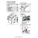
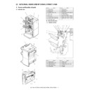
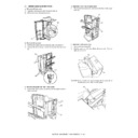
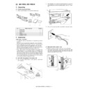
1) Open the front cover.
2) Pull out the stitcher base unit to the front, and pull the stitcher
2) Pull out the stitcher base unit to the front, and pull the stitcher
handle [1] once and raise the stitcher.
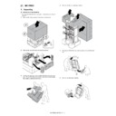
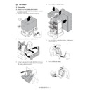
3) Remove the three screws [2], and remove the stitcher cover
[3].
4)
Remove the positioning tool [4] attached to the back of the
cover.
cover.
5)
For adjustment of the stitcher in the front side, remove the front
guide plate [5] and the center guide plate [6]. For adjustment of
the stitch in the rear side, remove the center guide plate [6]
and the rear guide plate [7]. (one screw, each)
guide plate [5] and the center guide plate [6]. For adjustment of
the stitch in the rear side, remove the center guide plate [6]
and the rear guide plate [7]. (one screw, each)
6)
For adjustment of the stitcher in the front side, loosen the two
screws [9] of the stitcher base [8]. For adjusting of the stitcher
in the rear side, loosen the two screws [10] of the stitcher base
[8].
screws [9] of the stitcher base [8]. For adjusting of the stitcher
in the rear side, loosen the two screws [10] of the stitcher base
[8].
7)
Insert the tool [12] into the staple slot of the stitcher [11].
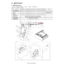
Bit setting of DIPSW1
Set value
(Unit:0.5 mm)
Bit 6
Bit 7
Bit 8
OFF
ON
ON
+3
OFF
ON
OFF
+2
OFF
OFF
ON
+1
OFF
OFF
OFF
0
ON
OFF
ON
-1
ON
ON
OFF
-2
ON
ON
ON
-3
Bit 6
Bit 7
Bit 8
ON
OFF
OFF
[2]
[3]
[1]
[4]
[7]
[6]
[5]
[10]
[9]
[8]
[11]
[12]
MX-FNX4 ADJUSTMENTS 8 – 4
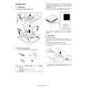
8) Tilt the stitcher. Then, rotate the stitch gear [13], fit the tool [14]
and the concave section of the base [15], and tighten the
screw of the base [15] to fix.
screw of the base [15] to fix.
2. Punch module (MX-PNX2A/B/C/D)
A. Adjusting the punch hole position (feed
direction)
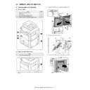
To enter the service mode, turn ON the power supply while the
dipswitch1 of FIN is ON.
dipswitch1 of FIN is ON.
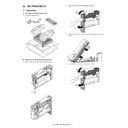
B. Adjusting the sensor output
Perform the following when the punch control PCB, transmission
sensor (photosensor PCB/LED PCB), or reflection sensor (waste
full photosensor PCB unit) has been replaced.
1) Remove the rear cover of the puncher after ensuring that the
sensor (photosensor PCB/LED PCB), or reflection sensor (waste
full photosensor PCB unit) has been replaced.
1) Remove the rear cover of the puncher after ensuring that the
power supply of the host machine is OFF.
2) Set the SW601 of the punch control PCB as shown below.
3) Turn ON the host machine.
4) Press the SW602 on the punch control PCB. The sensor out-
4) Press the SW602 on the punch control PCB. The sensor out-
put is automatically adjusted.
* The adjustment is complete when the LED 601 and LED 602
* The adjustment is complete when the LED 601 and LED 602
on the punch control PCB blink alternately.
5) Press the SW602 or SW603 on the punch control PCB to end
the adjustment mode. Then, set all the bits of the SW601 to
OFF.
OFF.
6) Turn OFF the host machine.
C. Registering the number of punch holes
Perform the following to register the type of punch module (number
of holes) used to the IC on the punch control PCB for identification
by the finisher. Be sure to register the type whenever you have
replaced the punch control PCB.
1) Remove the rear cover of the puncher after ensuring that the
of holes) used to the IC on the punch control PCB for identification
by the finisher. Be sure to register the type whenever you have
replaced the punch control PCB.
1) Remove the rear cover of the puncher after ensuring that the
power supply to the host machine is turned OFF.
2) Set the SW601 of the punch control PCB as shown below.
3) Turn ON the host machine.
4) Press the SW602 on the punch control PCB to select your
4) Press the SW602 on the punch control PCB to select your
desired number of punch holes.
* Each press on SW602 moves the selection through the fol-
* Each press on SW602 moves the selection through the fol-
lowing (repeatedly from top to bottom).
5)
Press the SW603 on the punch control PCB. Then, the num-
ber of punch holes is registered into the punch control PCB.
* The registration is complete when the LED 601 and LED
ber of punch holes is registered into the punch control PCB.
* The registration is complete when the LED 601 and LED
602 on the punch control PCB blink alternately.
6)
Press the SW602 or SW603 on the punch control PCB to end
the adjustment mode. Then, shift all the bits of the SW601 to
OFF.
the adjustment mode. Then, shift all the bits of the SW601 to
OFF.
7)
Turn OFF the host machine.
[15]
[14]
[13]
ON
1
2
3
4
ON
1
2
3
4
Number of punch holes
LED601/602
2 holes (punch module L1)
Blinks once in a cycle
2/3 holes (punch module M1)
Blinks twice in a cycle
4 holes (punch module N1 (FRA))
Blinks thrice in a cycle
4 holes (punch module P1 (SWD))
Blinks four times in a cycle
Display

