Sharp MX-5500N / MX-6200N / MX-7000N (serv.man50) Service Manual ▷ View online
MX-7000N ELECTRICAL SECTION 11 – 49
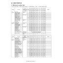
T1PED
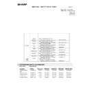
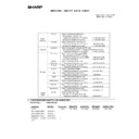
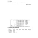
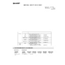
Tandem tray 1 sensor
[Photo interrupter]
[Photo interrupter]
Detects paper in the tandem
tray 1.
tray 1.
Paper NO
Paper YES
CN5
25
PCU
T1LUM
Paper tray lift-up motor
(Tandem tray 2)
[Brush motor]
(Tandem tray 2)
[Brush motor]
Drives the paper tray lift.
Stop
UP
CN6
17
PCU
T1PFC
Tandem tray 1 paper feed
clutch
[Electromagnetic clutch]
clutch
[Electromagnetic clutch]
Controls ON/OFF of the paper
feed tray in the tandem tray 1
paper feed section.
feed tray in the tandem tray 1
paper feed section.
ON
OFF
CN4
12
PCU
T1PPD1
Tandem tray 1 transport
sensor 1
[Reflection type sensor]
sensor 1
[Reflection type sensor]
Detects paper entry of
tandem tray 1.
tandem tray 1.
Pass
-
CN5
21
PCU
T1PPD2
Tandem tray 1 transport
sensor 2
[Reflection type sensor]
sensor 2
[Reflection type sensor]
Detects the tandem tray 1
paper pass in the transport
roller.
paper pass in the transport
roller.
Pass
-
CN5
17
PCU
T1PUS
Paper pickup solenoid
(Tandem tray 1)
[Electromagnetic solenoid]
(Tandem tray 1)
[Electromagnetic solenoid]
Paper pickup solenoid
(Tandem tray 1)
(Tandem tray 1)
ON
OFF
CN5
33
PCU
T1SPD
Tandem tray 1 paper
remaining quantity detector
[Photo interrupter]
remaining quantity detector
[Photo interrupter]
Detects the remaining
quantity of paper in the
tandem tray 1.
quantity of paper in the
tandem tray 1.
-
Remaining
quantity
66% or
less
CN5
29
PCU
T2LUD
Tandem tray 2 sensor
[Photo interrupter]
[Photo interrupter]
Detects the tandem tray 2 lift-
up.
up.
Upper limit
-
CN5
13
PCU
T2PED
Tandem tray 2 sensor
[Photo interrupter]
[Photo interrupter]
Detects paper in the tandem
tray 2.
tray 2.
Paper NO
Paper YES
CN5
15
PCU
T2LUM
Paper tray lift-up motor
(Tandem tray 2)
[Brush motor]
(Tandem tray 2)
[Brush motor]
Drives the paper feed tray lift.
Stop
UP
CN6
13
PCU
T2PFC
Tandem tray 2 paper feed
clutch
[Electromagnetic clutch]
clutch
[Electromagnetic clutch]
Controls ON/OFF of the paper
feed roller in the tandem tray
2 paper feed section.
feed roller in the tandem tray
2 paper feed section.
ON
OFF
CN4
10
PCU
T2PPD
Tandem tray 2 transport
detection
[Reflection type sensor]
detection
[Reflection type sensor]
Detects paper pass from the
tandem tray 2.
tandem tray 2.
Pass
-
CN3
9
PCU
T2PUS
Paper pickup solenoid
(Tandem tray 2)
[Electromagnetic solenoid]
(Tandem tray 2)
[Electromagnetic solenoid]
Paper pickup solenoid
(Tandem tray 2)
(Tandem tray 2)
ON
OFF
CN5
14
PCU
T2SPD
Tandem tray 2 paper
quantity detector [Photo
interrupter]
quantity detector [Photo
interrupter]
Detects the remaining
quantity of paper in the
tandem tray 2.
quantity of paper in the
tandem tray 2.
-
Remaining
quantity
66% or
less
CN5
27
PCU
TANCL
Tandem tray transport clutch
[Electromagnetic clutch]
[Electromagnetic clutch]
Controls ON/OFF of the paper
transport roller in the tandem
tray section.
transport roller in the tandem
tray section.
ON
OFF
CN4
8
PCU
TANDH
Tandem tray dehumidifying
heater
heater
Dehumidifies paper.
TANSET
Tandem tray installation
detection [Photo interrupter]
detection [Photo interrupter]
Detects insertion and removal
of the tandem tray.
of the tandem tray.
Pull our
Insertion
CN3
32
PCU
TBBOX
Waste toner box sensor
[Photo interrupter]
[Photo interrupter]
Detects installation of the
waste toner box.
waste toner box.
NO
Install
CN8
28
PCU
TBLTB
Transfer belt separation
sensor BK [Photo interrupter]
sensor BK [Photo interrupter]
Detects the transfer belt
separation BK.
separation BK.
-
BK position
CN15
4
PCU
TBLTC
Transfer belt separation
sensor Cl [Photo interrupter]
sensor Cl [Photo interrupter]
Detects the transfer belt
separation CL.
separation CL.
CL
position
-
CN9
18
PCU
TCS_C
Toner density detection C
(ATC) [Permeable sensor]
(ATC) [Permeable sensor]
Detects the toner density (C).
-
-
CN7
7
PCU
Analog
detection
detection
TCS_K
Toner density detection K
(ATC) [Permeable sensor]
(ATC) [Permeable sensor]
Detects the toner density (K).
-
-
CN9
19
PCU
Analog
detection
detection
TCS_M
Toner density detection M
(ATC) [Permeable sensor]
(ATC) [Permeable sensor]
Detects the toner density (M).
-
-
CN7
23
PCU
Analog
detection
detection
TCS_Y
Toner density detection Y
(ATC) [Permeable sensor]
(ATC) [Permeable sensor]
Detects the toner density (Y).
-
-
CN7
12
PCU
Analog
detection
detection
TFD
Main unit paper exit full
detection [Photo interrupter]
detection [Photo interrupter]
Detects the full state of the
face-down paper exit tray.
face-down paper exit tray.
Full
-
CN15
4
PCU
TFD_R
Right tray paper exit full
detection [Photo interrupter]
detection [Photo interrupter]
Detects the full state of the
right tray paper exit.
right tray paper exit.
Full
-
CN2
1
RD I/F
TH_EX1
Contact thermistor EX1
(External 1)
(External 1)
Detects the temperature of
the heat roller.
the heat roller.
-
-
CN12
14
PCU
Analog
detection
detection
TH_EX2
Contact thermistor EX2
(External 2)
(External 2)
Detects the temperature of
the heat roller.
the heat roller.
-
-
CN12
16
PCU
Analog
detection
detection
TH_LM
Contact thermistor (Lower
main)
main)
Detects the temperature of
the heat roller.
the heat roller.
-
-
CN12
12
PCU
Analog
detection
detection
TH_M
Manual feed temperature
detection
detection
Detects the temperature of
the manual feed tray and its
peripheral sections.
the manual feed tray and its
peripheral sections.
-
-
CN15
30
PCU
Analog
detection
detection
Signal name
Name [Type]
Function/Operation
Connector level
Connector
No.
Pin
No.
No.
PWB
name
NOTE
"L"
"H"
MX-7000N ELECTRICAL SECTION 11 – 50
TH_UM
Contact thermistor UM
(Upper Main)
(Upper Main)
Detects the temperature of
the heat roller.
the heat roller.
-
-
CN12
8
PCU
Analog
detection
detection
TH_US
Contact thermistor US
(Upper Sub)
(Upper Sub)
Detects the temperature of
the heat roller.
the heat roller.
-
-
CN12
10
PCU
Analog
detection
detection
TH1
LSU thermistor 1
[Temperature sensor]
[Temperature sensor]
Detects the temperature of
the LSU.
the LSU.
-
-
CN8
11
PCU
Analog
detection
detection
TH1_AD1/AD2
Non-contact thermistor
(Upper Main)
(Upper Main)
Detects the temperature of
the heat roller.
the heat roller.
-
-
CN12
16/2
PCU
Analog
detection
detection
TH2
LSU thermistor 2
[Temperature sensor]
[Temperature sensor]
Detects the temperature of
the LSU.
the LSU.
-
-
CN8
12
PCU
Analog
detection
detection
THPS
Secondary transfer
separation drive sensor
[Photo interrupter]
separation drive sensor
[Photo interrupter]
Detects separation of
secondary transfer.
secondary transfer.
-
Contact
CN18
8
PCU
TM_C
Toner motor C
[Synchronous motor]
[Synchronous motor]
Transports toner from the
toner cartridge to the
developing unit.
toner cartridge to the
developing unit.
-
-
CN10
27, 28
PCU
Drives with
2-phase signals.
2-phase signals.
TM_K1
Toner motor K1
[Synchronous motor]
[Synchronous motor]
Transports toner from the
toner cartridge to the
developing unit.
toner cartridge to the
developing unit.
-
-
CN10
23, 25
PCU
Drives with
2-phase signals.
2-phase signals.
TM_K2
Toner motor K2
[Synchronous motor]
[Synchronous motor]
Transports toner from the
toner cartridge to the
developing unit.
toner cartridge to the
developing unit.
-
-
CN10
19, 21
PCU
Drives with
2-phase signals.
2-phase signals.
TM_M
Toner motor M
[Synchronous motor]
[Synchronous motor]
Transports toner from the
toner cartridge to the
developing unit.
toner cartridge to the
developing unit.
-
-
CN10
20, 22
PCU
Drives with
2-phase signals.
2-phase signals.
TM_Y
Toner motor Y
[Synchronous motor]
[Synchronous motor]
Transports toner from the
toner cartridge to the
developing unit.
toner cartridge to the
developing unit.
-
-
CN10
24, 26
PCU
Drives with
2-phase signals.
2-phase signals.
TNFD
Waste toner full detection
[Photo interrupter]
[Photo interrupter]
Detects the full state of waste
toner.
toner.
-
Full
CN3
30
PCU
TRC1
Vertical transport clutch
upper
[Electromagnetic clutch]
upper
[Electromagnetic clutch]
Controls ON/OFF of the
vertical transport roller.
vertical transport roller.
ON
OFF
CN4
6
PCU
TRC2
Vertical transport clutch
lower
[Electromagnetic clutch]
lower
[Electromagnetic clutch]
Controls ON/OFF of the
vertical transport roller.
vertical transport roller.
ON
OFF
CN3
10
PCU
TURM
Secondary transfer
separation drive motor
[Brush motor]
separation drive motor
[Brush motor]
Performs separation in the
secondary transfer.
secondary transfer.
Stop
Separation/
Contact
CN18
6
PCU
VFM_C
Machine inside ventilation
fan motor (Center)
fan motor (Center)
Exhausts air from the
machine.
machine.
Drive
Stop
CN19
1
PCU
VFM_C_LD
Machine inside ventilation
fan motor (Center) lock
fan motor (Center) lock
Detects the machine inside
ventilation fan motor (center)
lock.
ventilation fan motor (center)
lock.
-
Lock
detected
CN18
29
PCU
VFM_R
Machine inside ventilation
fan motor (Right)
fan motor (Right)
Exhausts air from the
machine.
machine.
Stop
Drive
CN15
15
PCU
VFM_R_CNT
Machine inside ventilation
fan motor (Right) control
fan motor (Right) control
Controls the machine inside
ventilation fan motor (right)
RPM.
ventilation fan motor (right)
RPM.
-
-
CN15
17
PCU
PWM drive
VFM_R_LD
Machine inside ventilation
fan motor (Right) lock
fan motor (Right) lock
Detects the machine inside
ventilation fan motor (right)
lock.
ventilation fan motor (right)
lock.
-
Lock
detected
CN15
20
PCU
VTOD
Right transport unit open/
close sensor
[Photo interrupter]
close sensor
[Photo interrupter]
Detects open/close of the
right transport unit.
right transport unit.
Open
Close
CN3
20
PCU
WEB_END
Web end sensor
[Mechanical switch]
[Mechanical switch]
Detects the web end.
END
Detection
-
CN12
9
PCU
WEB_INL
Web presence detection
[Mechanical switch]
[Mechanical switch]
Detects presence of the web.
YES
NO
CN12
11
PCU
WEBM
Fusing web cleaning motor
[Synchronous motor]
[Synchronous motor]
Drives the fusing web
cleaning paper.
cleaning paper.
-
-
CN8
10, 12
Driver
Drives with
2-phase signals.
2-phase signals.
WH_SW
Dehumidifying heater SW
[Seesaw switch]
[Seesaw switch]
Controls ON/OFF of the
power of the dehumidifying
heater.
power of the dehumidifying
heater.
WTM_D
Waste toner drive motor
[DC brushless motor]
[DC brushless motor]
Stirs waste toner.
Drive
Stop
CN3
18
PCU
WTM_CLK
Waste toner drive motor
[DC brushless motor]
[DC brushless motor]
Controls the waste toner drive
motor RPM.
motor RPM.
-
-
CN3
16
PCU
PWM drive
WTM_LD
Waste toner drive motor lock
Detects the waste toner drive
motor lock.
motor lock.
-
Lock
detected
CN3
12
PCU
Signal name
Name [Type]
Function/Operation
Connector level
Connector
No.
Pin
No.
No.
PWB
name
NOTE
"L"
"H"
MX-7000N ELECTRICAL SECTION 11 – 51
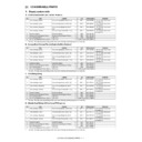
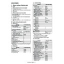
A. Combination of cassette paper size detection SW pattern and volume detection width
* SW numbers 1
→ 4: When viewed from the front.
(1) Tray 3
a. AB series
b. Inch series
c. China series
(2) Tray 4
a. AB series
b. Inch series
c. China series
C3 Rear edge detection SW
Width detection
volume paper width
(mm)
SS1
SS2
SS3
SS4
MIN
MAX
A3W
H
L
H
L
299
309
A3
H
L
L
L
291
303
A4
L
L
H
L
291
303
A4R
L
H
L
H
204
216
B4
H
L
L
H
251
263
B5
L
L
H
H
251
263
B5R
L
H
H
L
176
188
A5R
L
L
H
L
142.5
154.5
11 x 17
H
L
L
L
273.4
285.4
8.5 x 14
H
L
L
H
209.9
221.9
8.5 x 13
L
L
L
H
209.9
221.9
8.5 x 11
L
L
H
L
273.4
285.4
8.5 x 11R
L
H
L
L
209.9
221.9
Tray not-
installed
H
H
H
H
-
-
C3 Rear edge detection SW
Width detection
volume paper width
(mm)
SS1
SS2
SS3
SS4
MIN
MAX
A3W
H
L
H
L
299
309
A3
H
L
L
L
291
303
A4
L
L
H
L
291
303
A4R
L
H
L
H
204
216
B4
H
L
L
H
251
263
B5
L
L
H
H
251
263
11 x 17
H
L
L
L
273.4
285.4
8.5 x 14
H
L
L
H
209.9
221.9
8.5 x 13
L
L
L
H
209.9
221.9
8.5 x 11
L
L
H
L
273.4
285.4
8.5 x 11R
L
H
L
L
209.9
221.9
7.25 x 10.5R
L
H
H
L
178.1
190.1
5.5 x 8.5R
L
L
H
L
133.7
145.7
Tray not-
installed
H
H
H
H
-
-
C3 Rear edge detection SW
Width detection
volume paper width
(mm)
SS1
SS2
SS3
SS4
MIN
MAX
A3W
H
L
H
L
299
309
A3
H
L
L
L
291
303
A4
L
L
H
L
291
303
A4R
L
H
L
H
204
216
A5R
L
L
H
L
142.5
154.5
8.5 x 13
L
L
L
H
209.9
221.9
8K
H
L
L
H
264
276
16K
L
L
H
H
264
276
L
L
H
L
264
276
16KR
L
H
H
L
189
201
L
H
L
L
189
201
Tray not-
installed
H
H
H
H
-
-
C4 Rear edge detection SW
SS1
SS2
SS3
SS4
A3W
H
L
H
L
A3
H
L
L
L
A4
L
L
H
L
A4R
L
H
L
H
B4
H
L
L
H
B5
L
L
H
H
B5R
L
H
H
L
8.5 x 13
L
L
L
H
8.5 x 11R
L
H
L
L
Tray not-installed
H
H
H
H
C4 Rear edge detection SW
SS1
SS2
SS3
SS4
A3W
H
L
H
L
A4R
L
H
L
H
B5
L
L
H
H
11 x 17
H
L
L
L
8.5 x 14
H
L
L
H
8.5 x 13
L
L
L
H
8.5 x 11
L
L
H
L
8.5 x 11R
L
H
L
L
7.25 x 10.5R
L
H
H
L
Tray not-
installed
H
H
H
H
C4 Rear edge detection SW
SS1
SS2
SS3
SS4
A3W
H
L
H
L
A3
H
L
L
L
A4R
L
H
L
H
8.5 x 13
L
L
L
H
8K
H
L
L
H
16K
L
L
H
H
L
L
H
L
16KR
L
H
H
L
L
H
L
L
Tray not-
installed
H
H
H
H

