Sharp AR-PB2 (serv.man4) Service Manual ▷ View online
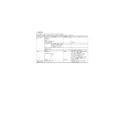
Mode
Control
Description
Duplex
Top
(Tablet Style)
(Tablet Style)
In Top Side (Tablet Style) binding
successive faces are bound on the
edges as shown below.
successive faces are bound on the
edges as shown below.
Simplex
Duplex
* Default
Limitations:
1) Binding Edge can only be selected for an entire print job.
2) Access to the three Binding Edge controls will be controlled by the
print drivers. Left and Top binding will be available in Custom &
PPD driver. Right binding will only be available in Custom driver.
PPD driver. Right binding will only be available in Custom driver.
(Interaction of Page Orientation and Binding Edge
for Duplex Printing)
for Duplex Printing)
There are a total of 6 combinations of Binding Edge and Page Orien-
tation settings, however, both Right and Left Edge Binding require the
same final page orientations and hence are combined. The 4 resul-
tant, unique duplex document appearances are shown below.
tation settings, however, both Right and Left Edge Binding require the
same final page orientations and hence are combined. The 4 resul-
tant, unique duplex document appearances are shown below.
Settings of Page
Orientation and
Binding Edge
Appearance of
Document
HP 5 Si
Nomenclature
1 Page Orientation:
Portrait
Binding Edge:
Left or Right (Book)
Binding Edge:
Left or Right (Book)
Portrait
Book
Book
2 Page Orientation:
Portrait
Binding Edge:
Top (Tablet)
Binding Edge:
Top (Tablet)
Portrait
Tablet
Tablet
3 Page Orientation:
Landscape
Binding Edge:
Top (Tablet)
Binding Edge:
Top (Tablet)
Landscape
Book
Book
4 Page Orientation:
Landscape
Binding Edge:
Left or Right (Book)
Binding Edge:
Left or Right (Book)
Landscape
Tablet
Tablet
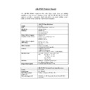
14. Memory Configuration
The following ROM are supported.
EPROM:
Boot & Simulation Program
Flash ROM: Program &Font data
Boot ROM is selectable between EPROM and Flash ROM #5 using
the jumper switching.
the jumper switching.
Flash ROM #5
4MB
Main Program
Flash ROM #5
3MB
PCL Roman 47 Fonts
PS Roman 35 Fonts
PS Roman 35 Fonts
Flash ROM #5
1MB
Boot/Simulation Program
ROM Memory Map
Physical Address
15. Printer control PWB switch (short pin)
and LED display
Switch, LED
Function
Switch
RESET switch
(SW102)
(SW102)
Processor and peripheral device
initialization
initialization
ABORT switch
(SW101)
(SW101)
MMI* generation to processor
LED
POWER-LED
(D114)
(D114)
PWB power ON. Lighted when
supplying power.
supplying power.
RUN-LED
(D113)
(D113)
Processor operating status.
Lights up when operating.
Lights up when operating.
Software
status
status
STO-LED
(D109)
(D109)
Lights UPD71055-A port 0 bit 4 at
"0."
"0."
ST1-LED
(D110)
(D110)
Lights UPD71055-A port 0 bit 5 at
"0."
"0."
ST2-LED
(D111)
(D111)
Lights UPD71055-A port 0 bit 6 at
"0."
"0."
ST3-LED
(D112)
(D112)
Lights UPD71055-A port 0 bit 7 at
"0."
"0."
Text
4 (even)
Text
3 (odd)
Text
2 (even)
Text
1 (odd)
Text
1 (odd)
Text
2 (even)
Text
3 (odd)
Text
4 (even)
Text
1 (odd)
Text
2 (even)
Text
3 (odd)
Text
4 (even)
Text
1 (odd)
Text
2 (even)
Text
3 (odd)
Text
4 (even)
T ext
text
Text
Tex
t
t
Text
Text
Text
text
PCL/PS Roman Fonts
0x0f80 0000
Main Program
0x1fc0 0000
Boot & Diag Program
0x1fff ffff
0x1fd0 0000
0x0f10 0000
0x0100 0000
Flash ROM #5
8MB
Power On Reset
Exception Vector
Exception Vector
EPROM 1MB(for DEBUG)
AR-PB2
8 – 8
(Error message)
F9
0
Content
ICU-PRT communication trouble
Detail
Cause
SCSI LSI abnormality
ICU PWB defect
SCSI connector connection defect
Printer PWB defect
ICU PWB defect
SCSI connector connection defect
Printer PWB defect
Check and remedy
Replace the printer PWB.
Check the SCSI connector.
Replace the printer PWB.
Replace the ICU PWB.
Check the SCSI connector.
Replace the printer PWB.
Replace the ICU PWB.
F9
01
Content
PRT DRAM trouble
Detail
DRAM trouble in the option printer board. (Check when turning on the power)
Cause
DRAM module is broken and access cannot be made.
DRAm module installation trouble
DRAm module installation trouble
Check and remedy
Check with SIM 57-1.
F9
02
Content
PRT Centro port check error
Detail
Option printer board Centro port trouble
Cause
Centro port defect
Printer PWB defect
Printer PWB defect
Check and remedy
Replace the printer board.
F9
03
Content
Network card trouble.
Detail
Network card self test trouble.
Cause
Network card defecft.
Printer PWB defect.
Network card connector connection defect.
Printer PWB defect.
Network card connector connection defect.
Check and remedy
Check the Network card connector.
Replace the printer PWB.
Replace the Network card.
Replace the printer PWB.
Replace the Network card.
F9
04
Content
Printer program error.
Detail
Program data trouble in the option printer board.
Cause
Flash memory data is destroied.
Check and remedy
Replace or rewrite the Flash memory.
Replace the printer PWB.
Replace the printer PWB.
F9
05
Content
Short of memory capacity on the ICU PWB
Detail
Total memory is less than 16MB on the ICU PWB.
Cause
Memory defect
SIMM memory connector connection defect
ICU PWB defect
Wrong type SIMM memory is installed
SIMM memory connector connection defect
ICU PWB defect
Wrong type SIMM memory is installed
Check and remedy
Replace the ICU PWB
Replace the memory
Replace the memory
F9
10
Content
PRT SCSI LSI abnormality
Detail
An error occurred in SCSI communication with the option printer board.
Cause
SCSI LSI abnormality
ICU PWB defect
Printer PWB defect
SCSI connector connection defect
ICU PWB defect
Printer PWB defect
SCSI connector connection defect
Check and remedy
Replace the printer PWB.
Check the SCSI connector.
Replace the printer PWB.
Replace the ICU PWB.
Check the SCSI connector.
Replace the printer PWB.
Replace the ICU PWB.
F9
90
Content
ICU-PRT communication trouble (PRT detection)
Detail
Cause
SCSI LSI abnormality
ICU PWB defect
SCSI connector connection defect
Printer PWB defect
ICU PWB defect
SCSI connector connection defect
Printer PWB defect
Check and remedy
Replace the printer PWB.
Check the SCSI connector.
Replace the printer PWB.
Replace the ICU PWB.
Check the SCSI connector.
Replace the printer PWB.
Replace the ICU PWB.
AR-PB2
q
Printed in Japan.
SHARP CORPORATION
Printing & Reprographic Systems Group
Quality & Reliability Control Center
Yamatokoriyama, Nara 639-1186, Japan
Printing & Reprographic Systems Group
Quality & Reliability Control Center
Yamatokoriyama, Nara 639-1186, Japan
1998 December Printed in Japan
N
AR-PB2

