Sharp MX-6500N / MX-7500N (serv.man11) Service Manual ▷ View online
MX-7500N ADJUSTMENTS AND SETTINGS 5 – 74
To execute the adjustment of the other item (Mode/Image),
press [EXECUTE] key.
After completion of all the adjustments of the items (Mode/
Image), press [OK] key, and the adjustment results are regis-
tered.
press [EXECUTE] key.
After completion of all the adjustments of the items (Mode/
Image), press [OK] key, and the adjustment results are regis-
tered.
11) Make a print, and check the print image quality.
(Refer to the item of the printer color balance and density
check.)
check.)
NOTE: Use SIM67-52 to reset the adjustment values to the default
values.
MX-7500N ADJUSTMENTS AND SETTINGS 5 – 75
9-F
(4)
Automatic color balance adjustment by the
user (Printer color balance automatic
adjustment ENABLE setting and
adjustment) (Normally unnecessary to the
setting change)
Automatic color balance adjustment by the
user (Printer color balance automatic
adjustment ENABLE setting and
adjustment) (Normally unnecessary to the
setting change)
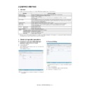
a. General
In the user program mode, the user can execute the auto color cal-
ibration (auto adjustment of the printer color balance and density).
This adjustment is to set Enable/Disable of the above user opera-
tion with SIM 26-53.
In the user program mode, the user can execute the auto color cal-
ibration (auto adjustment of the printer color balance and density).
This adjustment is to set Enable/Disable of the above user opera-
tion with SIM 26-53.
CAUTION: This setting must be set to ENABLE only when the
user's understanding on the automatic adjustment of
the copy color balance and density and the user's oper-
ational ability are judged enough to execute the adjust-
ment.
When set to enable, operation procedures must be fully
explained to the user.
the copy color balance and density and the user's oper-
ational ability are judged enough to execute the adjust-
ment.
When set to enable, operation procedures must be fully
explained to the user.
b. Setting procedure
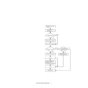
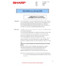
1) Enter the SIM 26-53 mode.
1) Enter the SIM 26-53 mode.
2) Select ENABLE or DISABLE with 10-key.
When disabling, set to "0" (NO). When enabling, set to "1"
(Yes).
(Yes).
3) Press [OK] key.
When set to DISABLE, the menu of the user auto color calibration
(automatic adjustment of printer color balance and density) is not
displayed in the user program mode.
When set to DISABLE, the menu of the user auto color calibration
(automatic adjustment of printer color balance and density) is not
displayed in the user program mode.
(Auto color calibration by the user (Auto color balance adjust-
ment))
ment))
CAUTION: This adjustment is based on the service target color bal-
ance set with SIM 67-27 or SIM 67-28. If, therefore, the
above settings are not properly performed, this adjust-
ment cannot be made properly.
above settings are not properly performed, this adjust-
ment cannot be made properly.
1)
Enter the system setting mode.
2)
Enter the printer setting mode.
3)
Press the auto color calibration key.
4)
Press [EXECUTE] key.
The color patch image (adjustment pattern) is printed out.
The color patch image (adjustment pattern) is printed out.
5)
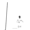
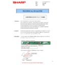
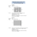
Set the color patch image (adjustment pattern) printed in pro-
cedure 4) on the document table.
Set the patch image so that the thin line is on the left side as
shown in the figure.
At that time, place 5 sheets of white paper on the above color
patch image (adjustment pattern).
cedure 4) on the document table.
Set the patch image so that the thin line is on the left side as
shown in the figure.
At that time, place 5 sheets of white paper on the above color
patch image (adjustment pattern).
6)
Press [EXECUTE] key, and the printer color balance adjust-
ment is executed automatically.
The message, "Will you go on to the copy color balance
adjustment?" is displayed.
To execute the copy color balance adjustment successively,
perform the procedures same as the above.
ment is executed automatically.
The message, "Will you go on to the copy color balance
adjustment?" is displayed.
To execute the copy color balance adjustment successively,
perform the procedures same as the above.
ADJ 10
Manual paper feed tray paper
size (width) sensor adjustment
size (width) sensor adjustment
This adjustment must be performed in the following cases:
* The manual paper feed tray section has been disassembled.
* The manual paper feed tray unit has been replaced.
* U2 trouble has occurred.
* The PCU PWB has been replaced.
* The EEPROM of the PCU PWB has been replaced.
* The manual paper feed tray section has been disassembled.
* The manual paper feed tray unit has been replaced.
* U2 trouble has occurred.
* The PCU PWB has been replaced.
* The EEPROM of the PCU PWB has been replaced.
OK
10-key
ǂǂǂ6,08/$7,21ǂǂ12
&/26(
7(67
(1$%/,1*2)$8720$7,&&2/25&$/,%5$7,21
$˖
˷̚˹
˖&23<
<(6
12
$˖
˖35,17(5
<(6
12
%˖
2.
ǂǂǂ6,08/$7,21ǂǂ12
&/26(
7(67
(1$%/,1*2)$8720$7,&&2/25&$/,%5$7,21
$˖
˷̚˹
˖&23<
<(6
12
$˖
˖35,17(5
<(6
12
%˖
2.
Thin line
MX-7500N ADJUSTMENTS AND SETTINGS 5 – 76
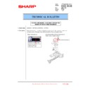
1) Enter the SIM 40-2 mode.
2)
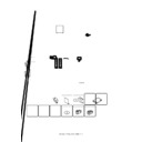
Open the manual paper feed guide to the maximum width posi-
tion.
tion.
3)
Press [EXECUTE] key.
[EXECUTE] key is highlighted. Then it returns to the normal
display.
The maximum width position detection level of the manual
paper feed guide is recognized.
[EXECUTE] key is highlighted. Then it returns to the normal
display.
The maximum width position detection level of the manual
paper feed guide is recognized.
4)
Set the manual paper feed guide to the A4 size.
5)
Press [EXECUTE] key.
[EXECUTE] key is highlighted. Then it returns to the normal
display.
The A4 size width position detection level of the manual paper
feed guide is recognized.
[EXECUTE] key is highlighted. Then it returns to the normal
display.
The A4 size width position detection level of the manual paper
feed guide is recognized.
6)
Set the manual paper feed guide to the width for the A4R size.
7)
Press [EXECUTE] key.
[EXECUTE] key is highlighted. Then it returns to the normal
display.
Set the manual paper feed guide to the width for the A4R size.
[EXECUTE] key is highlighted. Then it returns to the normal
display.
Set the manual paper feed guide to the width for the A4R size.
8)
Open the manual paper feed guide to the minimum width posi-
tion.
tion.
9)
Press [EXECUTE] key.
[EXECUTE] key is highlighted. Then it returns to the normal
display.
The minimum width position detection level of the manual
paper feed guide is recognized.
[EXECUTE] key is highlighted. Then it returns to the normal
display.
The minimum width position detection level of the manual
paper feed guide is recognized.
If the above operation is not completed normally, "ERROR" is dis-
played.
When the operation is completed normally, the above data are
saved to the memory and "COMPLETE" is displayed.
played.
When the operation is completed normally, the above data are
saved to the memory and "COMPLETE" is displayed.
EXECUTE
EXECUTE
Repeat the above procedure to adjust
the A4R width MIN POSITION.
the A4R width MIN POSITION.
ǂǂǂ6,08/$7,21ǂǂ12
&/26(
7(67
%<3$6675$<$'-8670(17
(;(&87(
0$;326,7,21$'-8670(17
35(66>(;(&87(@7267$57
ǂǂǂ6,08/$7,21ǂǂ12
&/26(
7(67
%<3$6675$<$'-8670(17
(;(&87(
0$;326,7,21$'-8670(17
(;(&87,1*
ǂǂǂ6,08/$7,21ǂǂ12
&/26(
7(67
%<3$6675$<$'-8670(17
(;(&87(
3
$
326,7,21$'-8670(17
35(66>(;(&87(@7267$57
ǂǂǂ6,08/$7,21ǂǂ12
&/26(
7(67
%<3$6675$<$'-8670(17
(;(&87(
&203/(7(
MX-7500N ADJUSTMENTS AND SETTINGS 5 – 77
ADJ 11
DSPF tray paper size (width)
sensor adjustment
sensor adjustment
This adjustment must be performed in the following cases:
* The DSPF paper feed tray section has been disassembled.
* The DSPF paper feed tray unit has been replaced.
* When a U2 trouble occurs.
* The scanner PWB has been replaced.
* The EEPROM on the scanner PWB has been replaced.
1) Enter the SIM 53-6 mode.
* The DSPF paper feed tray section has been disassembled.
* The DSPF paper feed tray unit has been replaced.
* When a U2 trouble occurs.
* The scanner PWB has been replaced.
* The EEPROM on the scanner PWB has been replaced.
1) Enter the SIM 53-6 mode.
2) Open the DSPF paper feed guide to the maximum width posi-
tion.
3) Press [EXECUTE] key.
The maximum width detection level is recognized.
4) Open the DSPF paper feed guide to the width for the A4R size.
5) Press [EXECUTE] key.
5) Press [EXECUTE] key.
The A4R width detection level is recognized.
6) Open the DSPF paper feed guide to the width for the A5R size.
7) Press [EXECUTE] key.
7) Press [EXECUTE] key.
The A5R width detection level is recognized.
8) Open the DSPF paper feed guide to the minimum width posi-
tion.
9) Press [EXECUTE] key.
The minimum width detection level is recognized.
When each of the above operations has been completed, the
"COMPLETE" message appears; when any of the operations has
failed, the "ERROR" message appears.
"COMPLETE" message appears; when any of the operations has
failed, the "ERROR" message appears.
ADJ 12
Document size detection
adjustment
adjustment
This adjustment must be performed in the following cases:
* When the original size sensor section has been disassembled.
* When the original size sensor section has been replaced.
* When U2 trouble has occurred.
* When the scanner control PWB is replaced.
* When the EEPROM on the scanner control PWB is replaced.
* When the original size sensor section has been disassembled.
* When the original size sensor section has been replaced.
* When U2 trouble has occurred.
* When the scanner control PWB is replaced.
* When the EEPROM on the scanner control PWB is replaced.
12-A
Document size sensor detection point
adjustment
adjustment
1)
Enter the SIM 41-1 mode.
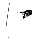
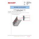
Loosen the original cover switch actuator adjustment screw
and slide the actuator position so that the display OCSW is
returned to the normal display when the height of the arm unit
top from the table glass is 20.2 +/- 0.25mm by slowly tilting the
document detection arm unit in the arrow direction and adjust.
(If the ON timing of the original cover switch is shifted, the doc-
ument detection function may malfunction.)
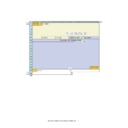
ǂǂǂ6,08/$7,21ǂǂ12
&/26(
7(67
63)75$<$'-8670(17
(;(&87(
75$<92/0$;75$<$'-8670(17
35(66>(;(&87(@7267$57
ǂǂǂ6,08/$7,21ǂǂ12
&/26(
7(67
3'6(1625&+(&.
2&6:
3'
3'
3'
3'
3'
3'
3'
32 0.5mm
+
-

