|
MX-6500N MX-7500N (serv.man152)
MX-7500 NVM RAM Data
-Document-
|
|
246.46 KB
|

|
MX-6500N MX-7500N (serv.man153)
NVRAM MX 6500
-Document-
|
|
244.6 KB
|
|
|
MX-6500N MX-7500N (serv.man10)
Installation Manual (Revised May 2017).
Service Manual
|
127
|
46.6 MB
|
|
|
MX-6500N MX-7500N (serv.man11)
Service Manual (Revised May 2017).
Service Manual
|
127
|
88.55 MB
|
|
|
MX-6500N MX-7500N (serv.man12)
Updated February 2014
Service Manual
|
127
|
53.08 MB
|
|
|
MX-6500N MX-7500N (serv.man13)
Covers
Service Manual
|
5
|
495.24 KB
|
|
|
MX-6500N MX-7500N (serv.man14)
Note for Servicing
Service Manual
|
3
|
288.72 KB
|
|
|
MX-6500N MX-7500N (serv.man15)
Section 1 Product Outline
Service Manual
|
2
|
90.39 KB
|
|
|
MX-6500N MX-7500N (serv.man16)
Section 2 Specifications
Service Manual
|
11
|
242.4 KB
|
|
|
MX-6500N MX-7500N (serv.man17)
Section 3 Consumable Parts
Service Manual
|
8
|
168.24 KB
|
|
|
MX-6500N MX-7500N (serv.man18)
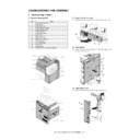
Section 4 External view and Internal Structure
Service Manual
|
27
|
9.46 MB
|
|
|
MX-6500N MX-7500N (serv.man19)
Section 5 Adjustments and Settings
Service Manual
|
98
|
5.74 MB
|
|
|
MX-6500N MX-7500N (serv.man20)
Section 6 Simulation
Service Manual
|
127
|
1.13 MB
|
|
|
MX-6500N MX-7500N (serv.man21)
Section 7 Troubleshooting
Service Manual
|
66
|
561.77 KB
|
|
|
MX-6500N MX-7500N (serv.man22)
Section 8 Firmware Update
Service Manual
|
5
|
624.57 KB
|
|
|
MX-6500N MX-7500N (serv.man23)
Section 9 Maintenance
Service Manual
|
32
|
4.5 MB
|
|
|
MX-6500N MX-7500N (serv.man24)
Section 10 Disassembly and Assembly
Service Manual
|
76
|
46.9 MB
|
|
|
MX-6500N MX-7500N (serv.man25)
Section 11 Various Storage Data Handling
Service Manual
|
19
|
273.65 KB
|
|
|
MX-6500N MX-7500N (serv.man26)
Section 12 Service Web Page
Service Manual
|
6
|
602.81 KB
|
|
|
MX-6500N MX-7500N (serv.man27)
Section 13 Operational Descriptions
Service Manual
|
53
|
8.03 MB
|
|
|
MX-6500N MX-7500N (serv.man28)
Section 14 Electrical Section
Service Manual
|
43
|
1.46 MB
|
|
|
MX-6500N MX-7500N (serv.man29)
Section 15 Service Tool
Service Manual
|
1
|
14.46 KB
|
|
|
MX-6500N MX-7500N (serv.man30)
Circuit Diagram
Service Manual
|
127
|
10.27 MB
|

|
MX-6500N MX-7500N (serv.man34)
File 001 - The size of each file is very large (approximately 100MB). First, download the files from File-1 to File-7 and Restoration File. Unzip the files from File-1 to File-7 on the same folder, and then run Restoration File (MERGE.BAT).
User Manual / Operation Manual
|
|
81.67 MB
|

|
MX-6500N MX-7500N (serv.man35)
File 002
User Manual / Operation Manual
|
|
82.14 MB
|

|
MX-6500N MX-7500N (serv.man36)
File 003
User Manual / Operation Manual
|
|
93.38 MB
|

|
MX-6500N MX-7500N (serv.man37)
File 004
User Manual / Operation Manual
|
|
94.42 MB
|

|
MX-6500N MX-7500N (serv.man38)
File 005
User Manual / Operation Manual
|
|
94.33 MB
|

|
MX-6500N MX-7500N (serv.man39)
File 006
User Manual / Operation Manual
|
|
94.43 MB
|

|
MX-6500N MX-7500N (serv.man40)
File 007 Restoration File
User Manual / Operation Manual
|
|
45.71 MB
|

|
MX-6500N MX-7500N (serv.man41)
MX7500N Operation Manual (HTML) - Revised February 2014
User Manual / Operation Manual
|
|
43.2 MB
|
|
|
MX-6500N MX-7500N (serv.man31)
Parts Guide (Revised July 2014).
Service Manual / Parts Guide
|
127
|
52.47 MB
|
|
|
MX-6500N MX-7500N (serv.man32)
Parts Guide For MX-PX10
Service Manual / Parts Guide
|
8
|
568.67 KB
|
|
|
MX-6500N MX-7500N (serv.man33)
Revised February 2014
Service Manual / Parts Guide
|
40
|
483.57 KB
|
|
|
MX-6500N MX-7500N (serv.man8)
Sharp Media Guide
Service Manual / Specification
|
54
|
2.6 MB
|
|
|
MX-6500N MX-7500N (serv.man9)
Section 2 Specifications
Service Manual / Specification
|
11
|
242.4 KB
|
|
|
MX-6500N MX-7500N (serv.man52)
CCE1848-PARTS MODIFICATION FOR COMMON USE WITH OTHER MODELS, ADU REVERSE GUIDE AND PAWLS
Service Manual / Technical Bulletin
|
3
|
245.29 KB
|
|
|
MX-6500N MX-7500N (serv.man53)
CCE1833-CHANGE OF FUSING BELT FUSING ROLLER FOR SPECIAL FUSER (CCE-1631)
Service Manual / Technical Bulletin
|
2
|
235.62 KB
|
|
|
MX-6500N MX-7500N (serv.man54)
CCE1832-PARTS CHANGE FOR COMMON USE WITH OTHER MODELS
Service Manual / Technical Bulletin
|
7
|
558.71 KB
|
|
|
MX-6500N MX-7500N (serv.man55)
CCE1820-PARTS CHANGE FOR COMMON USE WITH OTHER MODELS
Service Manual / Technical Bulletin
|
4
|
377.94 KB
|
|
|
MX-6500N MX-7500N (serv.man56)
CCE1815-PARTS CHANGE FOR COMMON USE WITH OTHER MODELS
Service Manual / Technical Bulletin
|
2
|
266.45 KB
|
|
|
MX-6500N MX-7500N (serv.man57)
CCE1814-PARTS CHANGE FOR COMMON USE WITH OTHER MODELS
Service Manual / Technical Bulletin
|
5
|
360.2 KB
|
|
|
MX-6500N MX-7500N (serv.man58)
CCE-1829 MODIFICATION OF PARTS DESIGN
Service Manual / Technical Bulletin
|
2
|
305 KB
|
|
|
MX-6500N MX-7500N (serv.man59)
Parts change for productivity improvement.
Service Manual / Technical Bulletin
|
3
|
184.15 KB
|
|
|
MX-6500N MX-7500N (serv.man60)
DESIGN CHANGE OF MF TRANSPORT PG
Service Manual / Technical Bulletin
|
2
|
249.36 KB
|
|
|
MX-6500N MX-7500N (serv.man61)
CHANGE OF CLUTCH
Service Manual / Technical Bulletin
|
3
|
291.4 KB
|
|
|
MX-6500N MX-7500N (serv.man62)
CCE 1785 DISCONTINUATION OF SUPPLY OF LAMP BASE
Service Manual / Technical Bulletin
|
4
|
400.71 KB
|
|
|
MX-6500N MX-7500N (serv.man63)
MODIFICATION OF DEVELOPER FILTER HOLDER UNIT
Service Manual / Technical Bulletin
|
2
|
209.53 KB
|
|
|
MX-6500N MX-7500N (serv.man64)
DESIGN CHANGE OF FUSING CENTER PAPER GUIDE
Service Manual / Technical Bulletin
|
2
|
301.38 KB
|
|
|
MX-6500N MX-7500N (serv.man65)
ADU PARTS CHANGE FOR COMMON USE WITH OTHER MODELS
Service Manual / Technical Bulletin
|
2
|
228.93 KB
|
|
|
MX-6500N MX-7500N (serv.man66)
DESIGN CHANGE OF DV DRIVE JOINT GEAR
Service Manual / Technical Bulletin
|
2
|
350.24 KB
|
|
|
MX-6500N MX-7500N (serv.man67)
RELEASE OF SERVICE PACK (SP) FOR GM1.1 OF EFI PRINT SERVER(MX-PE10)
Service Manual / Technical Bulletin
|
6
|
226.19 KB
|
|
|
MX-6500N MX-7500N (serv.man68)
CHANGE OF DOUBLE FEED PWB UNIT
Service Manual / Technical Bulletin
|
3
|
392.85 KB
|
|
|
MX-6500N MX-7500N (serv.man69)
MODIFICATION OF DELIVERY UNIT
Service Manual / Technical Bulletin
|
2
|
368.31 KB
|
|
|
MX-6500N MX-7500N (serv.man70)
FNS101_S FNS102_N Jams in MX-FN21 MX-FN22
Service Manual / Technical Bulletin
|
2
|
650.21 KB
|
|
|
MX-6500N MX-7500N (serv.man71)
SERVICE PARTS SET UP FOR RB14 ADU TRANSPORT UNIT
Service Manual / Technical Bulletin
|
2
|
264.91 KB
|
|
|
MX-6500N MX-7500N (serv.man72)
CHANGE OF MC FAN DUCT
Service Manual / Technical Bulletin
|
2
|
273.53 KB
|
|
|
MX-6500N MX-7500N (serv.man73)
CHANGE IN SHAPE OF FUSER SERARATE HOLDER
Service Manual / Technical Bulletin
|
2
|
171.9 KB
|
|
|
MX-6500N MX-7500N (serv.man74)
QTY CHANGE OF DUMPER SPRING OF DR POSITIONING UNIT
Service Manual / Technical Bulletin
|
2
|
422.3 KB
|
|
|
MX-6500N MX-7500N (serv.man75)
PARTS CHANGE OF PROCESS UNIT
Service Manual / Technical Bulletin
|
3
|
428.6 KB
|
|
|
MX-6500N MX-7500N (serv.man76)
PARTS MODIFICATION FOR COMMON USE WITH OTHER MODELS
Service Manual / Technical Bulletin
|
5
|
258.75 KB
|
|
|
MX-6500N MX-7500N (serv.man77)
ROM UPGRADE..... (6)
Service Manual / Technical Bulletin
|
1
|
67.01 KB
|
|
|
MX-6500N MX-7500N (serv.man78)
CHANGE OF SD CARD
Service Manual / Technical Bulletin
|
1
|
172.64 KB
|
|
|
MX-6500N MX-7500N (serv.man79)
CHANGE OF PARTS (FUSER FRAME) FOR COMMON USE WITH OTHER MODELS
Service Manual / Technical Bulletin
|
3
|
289.33 KB
|
|
|
MX-6500N MX-7500N (serv.man80)
PARTS CHANGE DUE TO COMMONALITY WITH NEW PRODUCT
Service Manual / Technical Bulletin
|
2
|
555.35 KB
|
|
|
MX-6500N MX-7500N (serv.man81)
Enhancement of LC13 Main Drive Gear
Service Manual / Technical Bulletin
|
3
|
760.63 KB
|
|
|
MX-6500N MX-7500N (serv.man82)
CHANGE OF MX-RB14 HINGE AND HINGE HOLDER
Service Manual / Technical Bulletin
|
2
|
135.92 KB
|
|
|
MX-6500N MX-7500N (serv.man83)
Change of PPD5 interface harness.
Service Manual / Technical Bulletin
|
2
|
108.01 KB
|
|
|
MX-6500N MX-7500N (serv.man84)
IMPROVEMENT FOR CONTAMINATION OF FOREIGN MATERIAL INTO FUSING ROLLER BEARING
Service Manual / Technical Bulletin
|
2
|
90.97 KB
|
|
|
MX-6500N MX-7500N (serv.man85)
NOISE AT FUSING DRIVE SECTION
Service Manual / Technical Bulletin
|
2
|
205.08 KB
|
|
|
MX-6500N MX-7500N (serv.man86)
SETUP OF FUSER SERVICE PARTS FOR IMAGE QUALITY ISSUES
Service Manual / Technical Bulletin
|
5
|
310.81 KB
|
|
|
MX-6500N MX-7500N (serv.man87)
ROM UPGRADE..... (5) Ver ICU 04.00.X1 PCU 03.00.X1
Service Manual / Technical Bulletin
|
5
|
86.41 KB
|
|
|
MX-6500N MX-7500N (serv.man88)
CHANGE IN SERVICE PARTS EXCLUSIVE FOR FIELD SUPPORT
Service Manual / Technical Bulletin
|
1
|
41.71 KB
|
|
|
MX-6500N MX-7500N (serv.man89)
CHANGE OF STANDARD FIXING POSITION OF FUSING FRONT LOWER PG
Service Manual / Technical Bulletin
|
1
|
128.21 KB
|
|
|
MX-6500N MX-7500N (serv.man90)
IMPROVEMENT FOR FLYWHEEL COMING OFF
Service Manual / Technical Bulletin
|
2
|
45.69 KB
|
|
|
MX-6500N MX-7500N (serv.man91)
CHANGE IN MATERIAL OF 1ST CLEANER JOINT GEAR
Service Manual / Technical Bulletin
|
2
|
141.57 KB
|
|
|
MX-6500N MX-7500N (serv.man92)
IMPROVEMENT OF IMAGE QUALITY ON HEAVY PAPER
Service Manual / Technical Bulletin
|
3
|
163.33 KB
|
|
|
MX-6500N MX-7500N (serv.man93)
ENHANCEMENT FOR PREVENTION OF DAMAGE ON HEAT ROLLER (2)
Service Manual / Technical Bulletin
|
3
|
172.99 KB
|
|
|
MX-6500N MX-7500N (serv.man94)
Notification of CPO (License Manager) and support for SHA-2.
Service Manual / Technical Bulletin
|
3
|
38.6 KB
|
|
|
MX-6500N MX-7500N (serv.man95)
CCE 1508 IMPROVEMENT OF PERFORMANCE WHEN OPENING CLOSING DSPF LOWER DOOR
Service Manual / Technical Bulletin
|
3
|
235.02 KB
|
|
|
MX-6500N MX-7500N (serv.man96)
Design change of delivery paper guide.
Service Manual / Technical Bulletin
|
2
|
91.45 KB
|
|
|
MX-6500N MX-7500N (serv.man97)
COUNTERMEASURES FOR GLOSSY LEVEL DIFFERENCE
Service Manual / Technical Bulletin
|
2
|
107.09 KB
|
|
|
MX-6500N MX-7500N (serv.man98)
ENHANCEMENT FOR PREVENTION OF DAMAGE ON HEAT ROLLER
Service Manual / Technical Bulletin
|
2
|
68.11 KB
|
|
|
MX-6500N MX-7500N (serv.man99)
COUNTERMEASURES FOR GLOSSY LEVEL DIFFERENCE
Service Manual / Technical Bulletin
|
3
|
379.16 KB
|
|
|
MX-6500N MX-7500N (serv.man100)
PCU ROM UPGRADE (4) ICU Ver 03.00.X100 - PCU Ver 02.01.X100
Service Manual / Technical Bulletin
|
1
|
74.67 KB
|
|
|
MX-6500N MX-7500N (serv.man101)
CHANGE IN COLOUR OF PIPE CUSHION
Service Manual / Technical Bulletin
|
2
|
60.13 KB
|
|
|
MX-6500N MX-7500N (serv.man102)
REMEDY FOR FLIPPING 1ST TRANSFER CLEANING BLADE
Service Manual / Technical Bulletin
|
2
|
376.75 KB
|
|
|
MX-6500N MX-7500N (serv.man103)
Starting Powder List (This list takes priority over information in Service Manuals).
Service Manual / Technical Bulletin
|
4
|
66.25 KB
|
|
|
MX-6500N MX-7500N (serv.man104)
CAUTION ILLUSTRATIONS ADDED TO PACKING BOX.
Service Manual / Technical Bulletin
|
1
|
83.72 KB
|
|
|
MX-6500N MX-7500N (serv.man105)
MANUAL FEED TRAY SHOWING 13 X 19 INSTEAD OF 320 x 450 WHEN USING SRA3 PAPER
Service Manual / Technical Bulletin
|
4
|
377.37 KB
|
|
|
MX-6500N MX-7500N (serv.man106)
REMEDY FOR TOOTH SKIPPING OF DV BELT
Service Manual / Technical Bulletin
|
3
|
340.09 KB
|
|
|
MX-6500N MX-7500N (serv.man107)
IMPROVEMENT FOR LOOSENING OF SCREWS FIXING FUSING REAR LOWER PG STAY AND FUSING REAR LOWER PG
Service Manual / Technical Bulletin
|
2
|
136.27 KB
|
|
|
MX-6500N MX-7500N (serv.man108)
COUNTERMEASURE FOR PAPER JAM (POD1 ETC.) TRIGGERED BY DECREASE IN HARDNESS OF FUSING ROLLER
Service Manual / Technical Bulletin
|
2
|
253.49 KB
|
|
|
MX-6500N MX-7500N (serv.man109)
COUNTERMEASURE FOR NOISE BY CLEARANCE OF JOINT SECTION BETWEEN DRIVE GEAR AND PARALLEL PIN
Service Manual / Technical Bulletin
|
1
|
76.27 KB
|
|
|
MX-6500N MX-7500N (serv.man110)
CAUTIONS WHEN INSERTING AND REMOVING THE HARNESS CONNECTOR DURING OPERATION PANEL INSTALLATION.
Service Manual / Technical Bulletin
|
2
|
111.5 KB
|
|
|
MX-6500N MX-7500N (serv.man111)
ROM UPGRADE ..... (3). Ver. 0300Xc00
Service Manual / Technical Bulletin
|
2
|
25.94 KB
|
|
|
MX-6500N MX-7500N (serv.man112)
COUNTERMEASURE FOR FUSER NOISE DUE TO ABRASION TO THE DRIVE GEAR 24T
Service Manual / Technical Bulletin
|
2
|
364.13 KB
|
|
|
MX-6500N MX-7500N (serv.man113)
CCE 1389R COUNTERMEASURE FOR E7-11 TROUBLE
Service Manual / Technical Bulletin
|
3
|
278.04 KB
|
|
|
MX-6500N MX-7500N (serv.man114)
NEWLY-REGISTERED SERVICE PARTS FOR FINSHERS
Service Manual / Technical Bulletin
|
5
|
931.93 KB
|
|
|
MX-6500N MX-7500N (serv.man115)
SETUP OF NEW SERVICE PARTS - PROCESS UNIT
Service Manual / Technical Bulletin
|
3
|
549.61 KB
|
|
|
MX-6500N MX-7500N (serv.man116)
Recommended shutdown procedure and Power Cycling of MFD
Service Manual / Technical Bulletin
|
1
|
186.43 KB
|
|
|
MX-6500N MX-7500N (serv.man118)
REMEDY FOR BLUR ON THE EDGE OF TEXTS
Service Manual / Technical Bulletin
|
2
|
101.21 KB
|
|
|
MX-6500N MX-7500N (serv.man119)
REMEDY FOR FLIPPING OF PRIMARY TRANSFER CLEANING BLADE AND NON-UNIFORM COLOUR DENSITY IN UNEVEN PITCH
Service Manual / Technical Bulletin
|
5
|
980.53 KB
|
|
|
MX-6500N MX-7500N (serv.man120)
ROM UPGRADE ..... (3) Ver 03.00.X100
Service Manual / Technical Bulletin
|
2
|
28.31 KB
|
|
|
MX-6500N MX-7500N (serv.man121)
MODIFICATION OF NOISE GENERATED BY CONTACT BETWEEN TENSION PLATE AND DRIVE TRANSPORT FRAME.
Service Manual / Technical Bulletin
|
2
|
208.65 KB
|
|
|
MX-6500N MX-7500N (serv.man122)
Countermeasure for E7-11 trouble.
Service Manual / Technical Bulletin
|
3
|
125.27 KB
|
|
|
MX-6500N MX-7500N (serv.man123)
CHANGE OF SHAPE FUSING REAR LOWER PAPER GUIDE COVER
Service Manual / Technical Bulletin
|
2
|
181.09 KB
|
|
|
MX-6500N MX-7500N (serv.man124)
COUNTERMEASURE TO REDUCE OPERATING NOISE OF PAPER FEED SOLENOID
Service Manual / Technical Bulletin
|
2
|
102.4 KB
|
|
|
MX-6500N MX-7500N (serv.man125)
Countermeasures against contamination of paper surface.
Service Manual / Technical Bulletin
|
2
|
24.64 KB
|
|
|
MX-6500N MX-7500N (serv.man126)
CHANGE OF MANUFACTURER OF CCD FFC
Service Manual / Technical Bulletin
|
2
|
192.74 KB
|
|
|
MX-6500N MX-7500N (serv.man127)
ADDITIONAL PROCEDURES WHEN INSTALLING MX-LCX3N TO MX6500N MX7500N
Service Manual / Technical Bulletin
|
2
|
387.19 KB
|
|
|
MX-6500N MX-7500N (serv.man128)
ADDITIONAL PROCEDURES WHEN INSTALLING MX-MF10 TO MX6500N MX7500N
Service Manual / Technical Bulletin
|
3
|
828.37 KB
|
|
|
MX-6500N MX-7500N (serv.man129)
CHANGE IN CONFIGURATION OF A SERVICE PART (TOUCH PANEL)
Service Manual / Technical Bulletin
|
1
|
71.65 KB
|
|
|
MX-6500N MX-7500N (serv.man130)
Modification of flash ROM for productivity improvement and parts communization
Service Manual / Technical Bulletin
|
2
|
285.53 KB
|
|
|
MX-6500N MX-7500N (serv.man131)
REMEDY FOR DEFECT IMAGES (VOID AREA) ON HEAVY PAPER AND GLOSS PAPER ETC.
Service Manual / Technical Bulletin
|
1
|
19.9 KB
|
|
|
MX-6500N MX-7500N (serv.man132)
Procedure for using Service Personnel Oriented Functions in Sharp Remote Device Manager.
Service Manual / Technical Bulletin
|
18
|
2.11 MB
|
|
|
MX-6500N MX-7500N (serv.man133)
ENGINE OFF CENTER ADJUSTMENT
Service Manual / Technical Bulletin
|
1
|
96.25 KB
|
|
|
MX-6500N MX-7500N (serv.man134)
IMPROVEMENT FOR FLYWHEEL COMING OFF
Service Manual / Technical Bulletin
|
2
|
108.46 KB
|
|
|
MX-6500N MX-7500N (serv.man135)
MX-FN22 Missing Front Staple on Double Staple Set.
Service Manual / Technical Bulletin
|
2
|
325.41 KB
|
|
|
MX-6500N MX-7500N (serv.man136)
A REMINDER TO TAKE EXTRA CARE WHILE DRAWING OUT AND INSERTING DV UNIT
Service Manual / Technical Bulletin
|
1
|
50.76 KB
|
|
|
MX-6500N MX-7500N (serv.man137)
MODIFICATION OF TOUCH PAD TO ENABLE WARM-UP FROM SLEEP MODE
Service Manual / Technical Bulletin
|
1
|
145.12 KB
|
|
|
MX-6500N MX-7500N (serv.man138)
MODIFICATION OF MX-PE10 FOR OPERATION PANEL DISPLAY FAILURE
Service Manual / Technical Bulletin
|
2
|
311.47 KB
|
|
|
MX-6500N MX-7500N (serv.man139)
ROM UPGRADE ..... (2). Ver 02.10.Xc00
Service Manual / Technical Bulletin
|
2
|
27.61 KB
|
|
|
MX-6500N MX-7500N (serv.man140)
JAM (POD1N ETC) AT FUSING REAR UPPER SEPARATE PLATE SECTION
Service Manual / Technical Bulletin
|
1
|
20.52 KB
|
|
|
MX-6500N MX-7500N (serv.man141)
ROM UPGRADE ..... (2). Ver. 02.00.X1.00
Service Manual / Technical Bulletin
|
2
|
30.16 KB
|
|
|
MX-6500N MX-7500N (serv.man142)
CHANGE OF PHOTO SENSOR
Service Manual / Technical Bulletin
|
2
|
111.52 KB
|
|
|
MX-6500N MX-7500N (serv.man143)
IMPROVEMENT OF DETECTION ACCURACY FOR DSPF TRANSPORT UPPER ACTUATOR.
Service Manual / Technical Bulletin
|
2
|
198.78 KB
|
|
|
MX-6500N MX-7500N (serv.man144)
ENHANCEMENT OF FLAPPER, FEED, UPPER IN TRANSPORT SECTION (MX-RB12)
Service Manual / Technical Bulletin
|
2
|
125.45 KB
|
|
|
MX-6500N MX-7500N (serv.man145)
CAUTION FOR REPLACEMENT OF FUSING DRIVE SHAFT TO REDUCE NOISE
Service Manual / Technical Bulletin
|
1
|
123.15 KB
|
|
|
MX-6500N MX-7500N (serv.man146)
IMPLEMENTATION OF COUNTERMEASURE AGAINST PAPER WRINKLE DURING FINISHER INSTALLATION
Service Manual / Technical Bulletin
|
1
|
191.42 KB
|
|
|
MX-6500N MX-7500N (serv.man147)
MX-FR43U DSK ROM UPGRADE..... (1). Ver 01.12.Xc00
Service Manual / Technical Bulletin
|
1
|
86.92 KB
|
|
|
MX-6500N MX-7500N (serv.man148)
ROM UPGRADE ..... (1). Ver 01.10.X1.00
Service Manual / Technical Bulletin
|
2
|
24.38 KB
|

|
MX-6500N MX-7500N (serv.man46)
Combined MFP Firmware Version ICU 04.00.X1 PCU 03.01.X1 - Refer To Bulletin Ref CCE-1694
Driver / Update
|
|
234.84 MB
|

|
MX-6500N MX-7500N (serv.man47)
Combined MFP Firmware Version ICU 04.00.X1 PCU 03.00.X1 - Refer To Bulletin Ref CCE-1632R
Driver / Update
|
|
234.92 MB
|

|
MX-6500N MX-7500N (serv.man48)
MX7500N Watermark Data - Ver WM_01.00.S1.00
Driver / Update
|
|
6.32 MB
|

|
MX-6500N MX-7500N (serv.man49)
Combined MFP Firmware Version ICU 03.00.X1 - PCU 02.01X100 - Refer To Bulletin Ref CCE-1495
Driver / Update
|
|
231.69 MB
|

|
MX-6500N MX-7500N (serv.man50)
Version ICU 03.00.Xc - Refer to Bulletin CCE-1444
Driver / Update
|
|
232.68 MB
|

|
MX-6500N MX-7500N (serv.man51)
MX7500N)- Firmware Version 02.03.S1 - Refer to Bulletin CCE-1320
Driver / Update
|
|
302.78 KB
|
|
|
MX-6500N MX-7500N
Administrator Machine Adjustment Guide Version 3
Handy Guide
|
41
|
4.82 MB
|
|
|
MX-6500N MX-7500N (serv.man2)
MX7040N - MX6500N - MX7500N Handy Guide Version 3.3 February 2016 - NOTE - Handy Guides are NOT a substitute for Service Manuals and Parts Guides
Handy Guide
|
68
|
6.24 MB
|
|
|
MX-6500N MX-7500N (serv.man3)
Adjustments to improve potential quality issues with different paper types
Handy Guide
|
7
|
615.28 KB
|
|
|
MX-6500N MX-7500N (serv.man4)
EEPROM Programming Procedure
Handy Guide
|
4
|
772.27 KB
|
|
|
MX-6500N MX-7500N (serv.man5)
MX-TM10 Handy Guide Version 1a June 2015 - NOTE - Handy Guides are NOT a substitute for Service Manuals and Parts Guides
Handy Guide
|
24
|
11.25 MB
|
|
|
MX-6500N MX-7500N (serv.man6)
PROCEDURE FOR CORRECTING FRONT FRAME TO REAR FRAME DENSITY PROBLEMS
Handy Guide
|
2
|
137.63 KB
|
|
|
MX-6500N MX-7500N (serv.man7)
Procedures For data back up And Restoration
Handy Guide
|
3
|
80.01 KB
|
|
|
MX-6500N MX-7500N (serv.man42)
Updated EEPROM Programming Procedure
FAQ
|
4
|
592.71 KB
|
|
|
MX-6500N MX-7500N (serv.man43)
MX-TM10 Volume Clarification
FAQ
|
1
|
249.36 KB
|
|
|
MX-6500N MX-7500N (serv.man44)
Procedure for selecting full bleed print from Fiery after creating A3 Paper in Paper catalogue
FAQ
|
10
|
2.41 MB
|

|
MX-6500N MX-7500N (serv.man45)
MX7500N Pantone LUT, How to Guide and application Support files. For use with Sharp Driver
FAQ
|
|
867.3 KB
|
|
|
MX-6500N MX-7500N (serv.man149)
MSDS for MX6500,MX7500,MX75GTYA Yellow Toner
Regulatory Data
|
4
|
42.08 KB
|
|
|
MX-6500N MX-7500N (serv.man150)
MSDS for MX6500,MX7500,MX75GTMA Magenta Toner
Regulatory Data
|
4
|
42 KB
|
|
|
MX-6500N MX-7500N (serv.man151)
MSDS for MX6500,MX7500,MX75GTCA Cyan Toner
Regulatory Data
|
4
|
42.07 KB
|

