Sharp AR-C260 (serv.man9) Service Manual ▷ View online
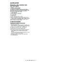
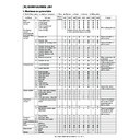
AR-C260/C260M EXTERNAL VIEW AND INTERNAL STRUCTURE 6 - 9
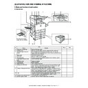
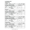
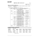
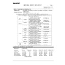
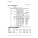
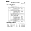
H. PWB 1
23
Manual feed paper length detection 1
Detects the paper length.
MPLD1
Photo sensor (Photo
transmission)
transmission)
24
Humidity sensor
Detects the ambient humidity.
HUD
—
25
No. 1 cassette paper feed detection
Detects paper exit from No. 1 paper tray.
PFD1
Photo sensor (Photo
transmission)
transmission)
26
Manual feed paper width detection
Detects the paper width.
MPWS
Volume (Variable
resistor)
resistor)
27
No. 1 cassette lift-up upper limit
detection
detection
Detects the upper limit position of paper.
LUD1
Photo sensor (Photo
transmission)
transmission)
28
PS front sensor
Detects paper in front of PS.
PPD2
Photo sensor (Photo
transmission)
transmission)
29
No. 1 cassette paper empty detection
Detects paper empty on the paper tray.
PED1
Photo sensor (Photo
transmission)
transmission)
30
Dehumidifier heater
Dehumidifier hater for the main body cassette. (Japan only)
DH
—
31
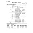
Belt lift-up upper limit detection
Detects lift-up or lift-down of the transfer belt.
BLUD
Photo sensor (Photo
transmission)
transmission)
32
Belt waste toner full detection
Detects belt waste toner full.
BTNF
Contact switch
33
Color toner concentration (process
control) sensor/Auto image Reg.
control) sensor/Auto image Reg.
Detects the toner patch density (color toner) in image density
correction operation. 2-sensors on PWB.
correction operation. 2-sensors on PWB.
PCS_C
Photo sensor (Photo
transmission)
transmission)
34
Lower heat roller thermistor
Detects the temperature on the heat roller surface.
THSD
Thermistor
35
Lower heat roller thermostat
Detects an abnormally high temperature and turns off the heater
lamp.
lamp.
HLTS2
Thermostat
Thermal switch
Thermal switch
36
Machine paper exit sensor 1
Detects discharged paper.
POD1
Photo sensor (Photo
transmission)
transmission)
37
Upper heat roller thermistor
Detects the temperature on the heat roller surface.
THSU
Thermistor
38
Upper heat roller thermostat
Detects an abnormally high temperature and turns off the heater
lamp.
lamp.
HLTS1
Thermostat
Thermal switch
Thermal switch
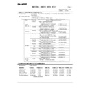
39
Main switch
Turns ON/OFF the main power.
MSW
Seesaw switch
40
Front door open detection
Detects open/close of the front door.
DSWF
Micro switch
41
Paper exit door open detection
Detects open/close of the paper exit door.
DSWL
Micro switch
42
Face-up paper exit tray full detection
Detects full of the face-up paper exit tray.
TFD
Photo sensor (Photo
transmission)
transmission)
43
Machine paper exit sensor 2
Detects discharged paper.
POD2
Photo sensor (Photo
transmission)
transmission)
44
Black toner concentration sensor
Detects black patch density for toner concentration
PCS_B
—
No.
Parts
Code, signal name
Type
Name
Function
1
2
5
6
3
4
8
7
9
10
12
11
13
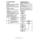
14
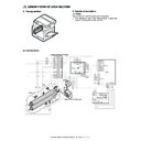
Front / right side / top view
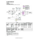
AR-C260/C260M EXTERNAL VIEW AND INTERNAL STRUCTURE 6 - 10
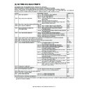
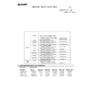
H. PWB2
No.
Parts
Code, signal name
Type
Name
Function
1
CL inverter PWB
Drives the xenon lamp.
2
MFP PWB
Corrects images from the CCD and controls the operation panel.
3
Flash PWB (OP)
Includes the program to drive the OP PWB.
4
Flash PWB (MFP)
Includes the program to drive the MFP PWB.
5
Document detection LED PWB
Emits light for document size detection.
6
CCD PWB
Converts document images into electric signals.
7
Lift-up unit PWB tray
Detects the cassette size and interfaces the cassette lift-up motor
signals.
signals.
8
Manual feed VR PWB
Outputs manual feed width signals.
9
Process control PWB (for
black)
black)
Outputs the black toner density on the transfer belt.
10
Process control PB (for color)
Outputs the color toner density on the transfer belt.
11
Document detection light
receiving PWB
receiving PWB
Outputs the document size detection signal.
12
Operation PWB
Outputs the key operation signal.
13
INV/LVDS PWB
Interfaces LCD from the MFPPWB and the touch panel signal,
and drives the LCD backlight.
and drives the LCD backlight.
14
Temp sensor PWB
Temp/humidity sensor readings.
No.
Parts
Code, signal name
Type
Name
Function
15
Flash PWB (ICU)
Includes the program to drive the ICU PWB.
16
ICU PWB
Performs image process and controls LED.
17
PCU PWB
Controls the engine section.
18
Driver PWB
Controls the DC load power and drive the motor.
19
AC power PWB
Controls the power on the primary side.
20
LED DL PWBs
Discharges electric charges on the OPC drums.
21
Flash PWB (PCU)
Includes the program to drive the PCU PWB.
22
High voltage TC PWB
Produces the transfer voltage.
23
DC power PWB
Outputs the voltage on the secondary side, and controls the
heater lamp.
heater lamp.
24
High voltage MC PWB
Produces a high voltage for the main charger and the developing
bias voltage.
bias voltage.
16
15
18
19
20
20
21
20
20
22
23
24
17
Right side / top rear / view

