Sharp AR-C260 (serv.man11) Service Manual ▷ View online
AR-C260/C260M SETTING AND ADJUSTMENTS 8 - 1
[8] SETTING AND ADJUSTMENTS
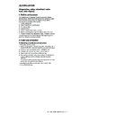
Each adjustment item in the adjustment item list is indicated with its JOB number.
Perform the adjustment procedures in the sequence of Job numbers from the smallest to the greatest.
However, there is no need to perform all the adjustment items. Perform only the necessary adjustments according to the need.
Unnecessary adjustments can be omitted. Even in this case, however, the sequence from the smallest to the greatest JOB number must be observed.
If the above precaution should be neglected, the adjustment would not complete normally or a trouble may occur.
*1: The simple adjustment does not use the adjustment jig. Its adjustment accuracy may be lower than that of the adjustment by using the adjustment
jig under some machine conditions.
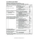
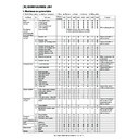
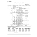
JOB No
ADJUSTMENT ITEM LIST
SIMULATION
ADJ 1
High voltage adjustment
ADJ 1A
Main charger grid voltage adjustment
8-2
ADJ 1B
DV bias voltage adjustment
8-1
ADJ 1C
Transfer voltage adjustment
8-6
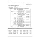
ADJ 2
Image density sensor adjustment
ADJ 2A
Color image density sensor adjustment (adjustment by the
adjustment jig)
adjustment jig)
44-13
ADJ 2B
Black image density sensor adjustment
44-2
ADJ 2C
Color image density sensor & black image density sensor
adjustment (Simple adjustment) *1
adjustment (Simple adjustment) *1
44-36
ADJ 3
Image focus, image skew adjustment (LED (writing) unit)
64-1/61-4
ADJ 4
Image registration adjustment
ADJ 4A
Image registration adjustment (Auto adjustment)
50-22
ADJ 4B
Image registration adjustment (Manual adjustment)
50-20
ADJ 5
Image position/print area adjustment
(Print engine section)
(Print engine section)
ADJ 5A
Main scanning direction image position adjustment
(Print engine section)
(Print engine section)
50-10
ADJ 5B
Sub scanning direction image position/print area adjustment
(Print engine section)
(Print engine section)
50-5
ADJ 6
Copy image distortion adjustment
ADJ 6A
Scanner (reading) unit parallelism adjustment
ADJ 6B
Copy image sub scanning direction distortion adjustment
ADJ 6C
Copy image main scanning direction distortion adjustment
ADJ 6D
Scan image distortion adjustment
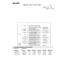
ADJ 7
Copy image focus (main scanning direction copy magnification ratio) adjustment (CCD unit position adjustment)
48-1
ADJ 8
Sub scanning direction copy magnification ratio adjustment
48-1
ADJ 9
Main scanning direction copy image position adjustment (Scanner (reading) section)
50-12
ADJ 10 Copy image position/image loss/void area adjustment
50-1/50-2
ADJ 11 Copy color balance/density adjustment
ADJ 11A
63-3 (63-5)
ADJ 11B
Copy color balance adjustment (Auto adjustment)
46-24
ADJ 11C Copy color balance adjustment (Manual adjustment)
46-21
ADJ 11D Copy density adjustment in low-density area
(Normally unnecessary to adjust.)
46-1/2
ADJ 11E
Copy color balance density adjustment (each copy mode)
(Normally unnecessary to adjust.)
(Normally unnecessary to adjust.)
46-10 to 16
ADJ 11F
63-9
ADJ 11G Image edge section gamma/density adjustment
(Black text and black line reproduction adjustment) (Normally
unnecessary to adjust.)
unnecessary to adjust.)
46-27
ADJ 11H Copy color balance adjustment (Single color Copy mode)
(Normally unnecessary to adjust.)
46-25
ADJ 11I
Auto color balance adjustment by user (Copy color balance
auto adjustment enable setting and adjustment)
auto adjustment enable setting and adjustment)
26-53
ADJ 11J
Background process conditions setting in the color auto copy
mode, image auto recognition conditions setting, text-on-dot
recognition conditions setting
mode, image auto recognition conditions setting, text-on-dot
recognition conditions setting
46-33
ADJ 12 Fusing pressure adjustment
ADJ 13 Fusing paper guide position adjustment
ADJ 14 Document size sensor adjustment
ADJ 14A
Original size sensor detection point adjustment
41-2
ADJ 14B
Original size sensor sensitivity adjustment
41-2
ADJ 15 Manual paper feed tray paper size sensor adjustment
40-2
ADJ 16 Touch panel coordinates setting
65-1
ADJ 17 Power voltage adjustment
ADJ 17A
3.4 V power voltage adjustment
ADJ 17B
5.0 V power voltage adjustment
ADJ 18 FAX/scanner mode image loss adjustment
50-27
AR-C260/C260M SETTING AND ADJUSTMENTS 8 - 2
Since the output voltage cannot be checked directly due to the
machine structure, the adjustment value of the simulation is set to the
default (specified value) to perform the adjustment.
machine structure, the adjustment value of the simulation is set to the
default (specified value) to perform the adjustment.
This adjustment must be performed in the following cases:
• When the high voltage power PWB is replaced.
• When a U2 trouble occurs.
• When the PCU PWB is replaced.
• When the EEPROM of the PCU PWB is replaced.
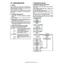
1) Enter the SIM 8-2 mode.
SIM 8-2
2) Select the output mode to be adjusted with the color key and scroll
key.
3) Enter the adjustment value (specified value), and press the [OK]
key.
By entering the default value (specified value), the specified volt-
age is outputted.
age is outputted.
Remark: When the default value is set, the specified voltage is output-
ted.
There is, therefore, no need to check the output voltage
unless there is a doubt for any abnormality in the output volt-
age.
If there is a need to check that the normal voltage is output-
ted or to adjust by referring to the output voltage, use the
method below.
There is, therefore, no need to check the output voltage
unless there is a doubt for any abnormality in the output volt-
age.
If there is a need to check that the normal voltage is output-
ted or to adjust by referring to the output voltage, use the
method below.
1) Remove the rear cover of the machine.
2) Remove the image process fan motor and the duct.
3) Connect the high voltage adjustment harnesses (DHAi-3471FCZZ/
DHAi-3472FCZZ) with the connectors CNMON and CNMONK on
the high voltage PWB.
the high voltage PWB.
4) Enter the SIM8-2 mode.
5) Select the output mode to be adjusted with the color key and the
scroll key.
6) Check that the pin numbers of the connectors CNMON and
CNMONK are properly assigned to the connector pin numbers of
the high voltage adjustment harness.
the high voltage adjustment harness.
7) Apply a digital multi-meter to the connector pins of the high voltage
adjustment harness corresponding to the output mode to be
adjusted.
adjusted.
ADJ 1
High voltage adjustment
ADJ 1A
Main charger grid voltage adjustment
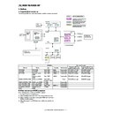
Color
Item Operation
mode
Adjustment value
Main charger grid voltage
Monitor (High voltage PWB)
Pin
No.
Actual
voltage
Adjustment
range
Specified
value
(Default)
Monitor voltage
(Specified value)
Connector
K
A: HIGH SPEED
High speed (140mm/s) (B & W)
180 – 700
620
53.5 ± 0.2v
CNMONK
1
–620v
B: MIDDLE SPEED
Middle speed (117mm/s) (Color) (B & W)
180 – 700
620
53.5 ± 0.2v
CNMONK
1
–620v
C: LOW SPEED
Low speed (58.5mm/s) (Color) (B & W)
(Special paper)
(Special paper)
180 – 700
590
50.6 ± 0.2v
CNMONK
1
–590v
C
A: MIDDLE SPEED
Middle speed (117mm/s) (Color) (B & W)
180 – 700
620
53.5 ± 0.2v
CNMON
3
–620v
B: LOW SPEED
Low speed (58.5mm/s) (Color) (B & W)
(Special paper)
(Special paper)
180 – 700
590
50.6 ± 0.2v
CNMON
3
–590v
M
A: MIDDLE SPEED
Middle speed (117mm/s) (Color) (B & W)
180 – 700
620
53.5 ± 0.2v
CNMON
7
–620v
B: LOW SPEED
Low speed (58.5mm/s) (Color) (B & W)
(Special paper)
(Special paper)
180 – 700
590
50.6 ± 0.2v
CNMON
7
–590v
Y
A: MIDDLE SPEED
Middle speed (117mm/s) (Color) (B & W)
180 – 700
620
53.5 ± 0.2v
CNMON
11
–620v
B: LOW SPEED
Low speed (58.5mm/s) (Color) (B & W)
(Special paper)
(Special paper)
180 – 700
590
50.6 ± 0.2v
CNMON
11
–590v
A
B
AR-C260/C260M SETTING AND ADJUSTMENTS 8 - 3
8) Press the [EXECUTE] key.
The main charger grid voltage is outputted for 30sec.
If this operation is performed for a long time, the OPC drum and
the developing roller may be damaged. Be careful to perform this
operation in a short time.
the developing roller may be damaged. Be careful to perform this
operation in a short time.
It is advisable to install an unnecessary developing unit and unnec-
essary OPC drums to the machine for this adjustment.
essary OPC drums to the machine for this adjustment.
9) Check the monitor voltage with the digital multi-meter.
If the monitor voltage is not in the above specified range, change
the adjustment value and adjust again. If the specified voltage is
not obtained even by changing the adjustment value, the following
parts may be judged as defective.
the adjustment value and adjust again. If the specified voltage is
not obtained even by changing the adjustment value, the following
parts may be judged as defective.
High voltage PWB
PCU PWB
Developing unit
Photoconductor unit
High voltage circuit electrode
This adjustment must be performed in the following cases:
• When the high voltage power PWB is replaced.
• When a U2 trouble occurs.
• When the PCU PWB is replaced.
• When the EEPROM of the PCU PWB is replaced.
1) Enter the SIM 8-1 mode.
SIM 8-1
2) Select the output mode to be adjusted with the color key and the
scroll key.
3) Enter the adjustment value (specified value), and press the [OK]
key.
By entering the default value (specified value), the specified volt-
age is outputted.
age is outputted.
Remark: When the default value is set, the specified voltage is output-
ted.
There is, therefore, no need to check the output voltage
unless there is a doubt for any abnormality in the output volt-
age.
If there is a need to check that the normal voltage is output-
ted or to adjust by referring to the output voltage, use the
method below.
There is, therefore, no need to check the output voltage
unless there is a doubt for any abnormality in the output volt-
age.
If there is a need to check that the normal voltage is output-
ted or to adjust by referring to the output voltage, use the
method below.
1) Remove the rear cover of the machine.
2) Remove the image process fan motor and the duct.
3) Connect the high voltage adjustment harnesses (DHAi-3471FCZZ/
DHAi-3472FCZZ) with the connectors CNMON and CNMONK on
the high voltage PWB.
the high voltage PWB.
4) Enter the SIM8-2 mode.
5) Select the output mode to be adjusted with the color key and the
scroll key.
6) Check that the pin numbers of the connectors CNMON and
CNMONK are properly assigned to the connector pin numbers of
the high voltage adjustment harness.
the high voltage adjustment harness.
ADJ 1B
DV bias voltage adjustment
Color
Item
Operation mode
Adjustment value
Developing bias voltage
Monitor (High voltage PWB)
Pin
No.
Actual
voltage
Adjustment
range
Specified
value
(Default)
Monitor voltage
(Specified value)
Connector
K
A: HIGH SPEED
High speed (140mm/s) (B & W)
180 – 700
315
7.43 ± 0.1V
CNMONK
3
–315v
B: MIDDLE SPEED
Middle speed (117mm/s) (Color) (B & W)
180 – 700
315
7.43 ± 0.1V
CNMONK
3
–315v
C: LOW SPEED
Low speed (58.5mm/s) (Color) (B & W)
(Special paper)
(Special paper)
180 – 700
285
6.45 ± 0.1V
CNMONK
3
–285v
C
A: MIDDLE SPEED
Middle speed (117mm/s) (Color) (B & W)
180 – 700
265
5.76 ± 0.1V
CNMON
1
–265v
B: LOW SPEED
Low speed (58.5mm/s) (Color) (B & W)
(Special paper)
(Special paper)
180 – 700
235
4.75 ± 0.1V
CNMON
1
–235v
M
A: MIDDLE SPEED
Middle speed (117mm/s) (Color) (B & W)
180 – 700
265
5.76 ± 0.1V
CNMON
5
–265v
B: LOW SPEED
Low speed (58.5mm/s) (Color) (B & W)
(Special paper)
(Special paper)
180 – 700
235
4.75 ± 0.1V
CNMON
5
–235v
Y
A: MIDDLE SPEED
Middle speed (117mm/s) (Color) (B & W)
180 – 700
240
4.75 ± 0.1V
CNMON
9
–240v
B: LOW SPEED
Low speed (58.5mm/s) (Color) (B & W)
(Special paper)
(Special paper)
180 – 700
210
3.78 ± 0.1V
CNMON
9
–210v
A
B
AR-C260/C260M SETTING AND ADJUSTMENTS 8 - 4
7) Apply a digital multi-meter to the connector pins of the high voltage
adjustment harness corresponding to the output mode to be
adjusted.
adjusted.
8) Press the [EXECUTE] key.
The developing bias voltage is outputted for 30sec.
If this operation is performed for a long time, the OPC drum and
the developing roller may be damaged. Be careful to perform this
operation in a short time.
the developing roller may be damaged. Be careful to perform this
operation in a short time.
It is advisable to install an unnecessary developing unit and unnec-
essary OPC drums to the machine for this adjustment.
essary OPC drums to the machine for this adjustment.
9) Check the monitor voltage with the digital multi-meter.
If the monitor voltage is not in the above specified range, change
the adjustment value and adjust again. If the specified voltage is
not obtained even by changing the adjustment value, the following
parts may be judged as defective.
the adjustment value and adjust again. If the specified voltage is
not obtained even by changing the adjustment value, the following
parts may be judged as defective.
High voltage PWB
PCU PWB
Developing unit
Photoconductor unit
High voltage circuit electrode
This adjustment must be performed in the following cases:
• When the high voltage power PWB is replaced.
• When a U2 trouble occurs.
• When the PCU PWB is replaced.
• When the EEPROM of the PCU PWB is replaced.
1) Enter the SIM 8-6 mode.
SIM 8-6
2) Select the mode to be adjusted with the color key and scroll key.
3) Enter the adjustment value (specified value), and press the [OK]
key.
By entering the default value (specified value), the specified volt-
age is outputted.
age is outputted.
Press the [EXECUTE] key to output the transfer voltage.
The image density sensor sections are of uneven quality in parts and
assembly. This causes variations in the absolute detection level
between machines. This adjustment (calibration) is performed to cor-
rect the variations.
assembly. This causes variations in the absolute detection level
between machines. This adjustment (calibration) is performed to cor-
rect the variations.
This adjustment is required in the following cases:
• When the image density sensor is replaced.
• When the transfer unit is replaced.
• When maintenance is performed.
• When U2 trouble occurs.
• When the PCU PWB is replaced.
• When the EEPROM on the PCU PWB is repalced.
The targets of the adjustment are the color image density sensor and
the black image density sensor. There are following adjustment meth-
ods:
the black image density sensor. There are following adjustment meth-
ods:
• Color image density sensor adjustment (adjustment by the adjust-
ment jig) SIM44-13
• Black image sensity sensor adjustment SIM44-2
• Image density sensor adjustment (The color image density sensor
and the black image density sensor are adjusted at the same time.)
(Simple adjustment) SIM44-36
(Simple adjustment) SIM44-36
Normally the following adjustments are executed:
• ADJ 2A Color image density sensor adjustment (adjustment by the
adjustment jig) (SIM44-13)
• ADJ 2B Black image density sensor adjustment (SIM44-2)
ADJ 1C
Transfer voltage adjustment
Item
Print mode
Standard setting value
(Default)
Adjustment
range
Output voltage (Kv)
K
C
M
Y
K
C
M
Y
A
PLAIN_SPX_CL
Color
Normal paper
117mm/s
173
159
132
132
51 - 255
2.4
2.4
2.4
2.4
B
PLAIN_DPX_CL
Color
Normal paper(Duplex mode)
117mm/s
188
173
142
142
2.7
2.7
2.7
2.7
C
OHP1_CL
Color
Transparency film 1
117mm/s
204
187
153
153
3
3
3
3
D
OHP2_CL
Color
Transparency film 2
58.5mm/s
137
150
153
163
1.7
2.2
3
3.3
E
HEAVY P1_SPX_CL
Color
Thick paper 1
58.5mm/s
158
146
122
122
2.1
2.1
2.1
2.1
F
HEAVY_P1_DPX_CL
Color
Thick paper 1(Duplex mode)
58.5mm/s
188
173
142
142
2.7
2.7
2.7
2.7
G
HEAVY_P2_CL
Color
Thick paper 2
58.5mm/s
173
159
132
132
2.2
2.2
2.2
2.2
H
ENV_CL
Color
Envelope
117mm/s
163
150
125
125
2.2
2.2
2.2
2.2
I
PLAIN_SPX_BW
B & W
Normal paper
140mm/s
168
2.3
J
PLAIN_DPX_BW
B & W
Normal paper(Duplex mode)
140mm/s
178
2.5
K
OHP1_BW
B & W
Transparency film 1
117mm/s
204
3
L
OHP2_BW
B & W
Transparency film 2
58.5mm/s
137
1.7
M
HEAVY_P1_SPX_BW
B & W
Thick paper 1
58.5mm/s
147
1.9
N
HEAVY_P1_DPX_BW
B & W
Thick paper 1(Duplex mode)
58.5mm/s
178
2.5
O
HEAVY_P2_BW
B & W
Thick paper 2
58.5mm/s
163
2.2
P
ENV_BW
B & W
Envelope
140mm/s
168
2.3
Color
Actual output variable range
Voltage change/Adjustment value (1) (Varying amount when the adjustment value is changed by 1)
K
0 to 4000V
About 19.6V
C
0 to 4500V
About 22.1V
M
0 to 6000V
About 29.4V
Y
0 to 6000V
About 29.4V
ADJ 2
Image density sensor adjustment

