Sharp AR-C260 (serv.man11) Service Manual ▷ View online
AR-C260/C260M SETTING AND ADJUSTMENTS 8 - 37
This adjustment must be performed in the following cases:
• When the original size sensor section is disassembled.
• When the original size sensor section is replaced.
• When a U2 trouble occurs.
• When the PCU main PWB is replaced.
• When the EEPROM of the PCU main PWB is replaced.
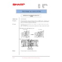
1) Enter the SIM 41-1 mode.
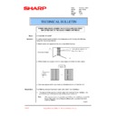
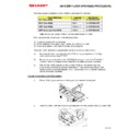
Gradually tilt the original detection arm unit. Loosen the original
cover switch actuator adjustment screw so that the highlight dis-
play of OCSW is turned to the normal display when the height of
the arm unit top from the table glass is 32 ± 0.5mm. Slide the actu-
ator to adjust. (If the ON timing of the original cover switch is
shifted, the original detection function may malfunction.)
1) Enter the SIM 41-2 mode.
2) Make the sensor adjustment without an original.
With the original cover open and without an original on the original
table, press the [EXECUTE] key.
table, press the [EXECUTE] key.
3) Place A3 (11 x 17) document on the document table and press the
[EXECUTE] key.
This adjustment must be performed in the following cases:
• When the manual paper feed tray section is disassembled.
• When the manual paper feed tray unit is replaced.
• When a U2 trouble occurs.
• When the PCU PWB is replaced.
• When the EEPROM of the PCU PWB is replaced.
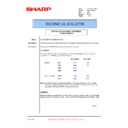
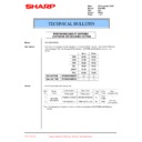
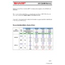
1) Enter the SIM 40-2 mode.
2) Set the manual paper feed guide to the maximum position.
3) Press the [EXECUTE] key.
The [EXECUTE] key is highlighted. Then it returns to the normal
display. The manual paper feed guide maximum width position
detection level is recognized.
display. The manual paper feed guide maximum width position
detection level is recognized.
4) Set the manual paper feed guide to A4 (11 x 8.5") size width.
5) Press the [EXECUTE] key.
The [EXECUTE] key is highlighted. Then it returns to the normal
display. The manual paper feed guide A4 (11 x 8.5") width position
detection level is recognized.
display. The manual paper feed guide A4 (11 x 8.5") width position
detection level is recognized.
6) Set the manual paper feed guide to A4R (11 x 8.5"R) size width.
7) Press the [EXECUTE] key.
The [EXECUTE] key is highlighted. Then it returns to the normal
display. The manual paper feed guide A4R (11 x 8.5" R) width
position detection level is recognized.
display. The manual paper feed guide A4R (11 x 8.5" R) width
position detection level is recognized.
8) Set the manual paper feed guide to the minimum position.
ADJ 14
Document size sensor
adjustment
adjustment
ADJ 14A
Original size sensor detection point
adjustment
adjustment
ADJ 14B
Original size sensor sensitivity
adjustment
adjustment
32 5mm
+
-
Original detection
arm unit
arm unit
Table glass
Original cover switch actuator
ADJ 15
Manual paper feed tray paper size
sensor adjustment
sensor adjustment
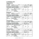
A6
A5
A5
A4
A4
A3
A3W
B5
B5
B4
5
1
/
2
7
1
/
4
11
12
8
1
/
2
A6
A5
A5
A4
A4
A3
A3W
B5
B5
B4
5
1
/
2
7
1
/
4
11
12
8
1
/
2
AR-C260/C260M SETTING AND ADJUSTMENTS 8 - 38
9) Press the [EXECUTE] key.
The [EXECUTE] key is highlighted. Then it returns to the normal
display. The manual paper feed guide minimum width position
detection level is recognized.
display. The manual paper feed guide minimum width position
detection level is recognized.
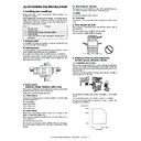
This adjustment must be performed in the following cases:
• When the operation panel is replaced.
• When a U2 trouble occurs.
• When the MFP PWB is replaced.
• When the EEPROM of the MFP PWB is replaced.
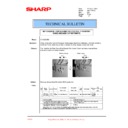
1) Enter the SIM 65-1 mode.
2) Touch the four cross marks on the display.
When the cross marks are pressed, the buzzer sounds and they
are changed into gray display. When the touch panel adjustment is
completed by pressing all the four marks, the display returns to the
simulation sub code number entry menu.
are changed into gray display. When the touch panel adjustment is
completed by pressing all the four marks, the display returns to the
simulation sub code number entry menu.
If there is any abnormality, the first display is shown again.
∗
When touching the crosses, never use a needle or a pin with a sharp
point.
point.
This adjustment must be performed in the following cases:
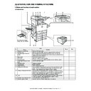
• When a part in the DC power unit is replaced.
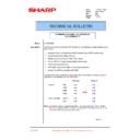
1) Put the multi-meter on the 3.4V line of the DC main PWB and
GND.
2) Turn VR701 on the DC main PWB to adjust so that the voltage is
3.4V.
1) Put the multi-meter on the 5.0V line of the DC main PWB and
GND.
2) Turn VR702 on the DC main PWB to adjust so that the voltage is
5.0V.
1) Enter the SIM 40-2 mode.
2) Select the adjustment mode with the scroll key.
3) Enter the adjustment value at the selected point with the 10-key
and press the OK key to set the entered adjustment value.
When the adjustment value is changed, the image losses at the four
corners are changed uniformly.
corners are changed uniformly.
ADJ 16
Touch panel coordinates setting
ADJ 17
Power voltage adjustment
VR701
VR702
ADJ 17A
3.4 V power voltage adjustment
ADJ 17B
5.0 V power voltage adjustment
ADJ 18
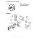
FAX/scanner mode image loss
adjustment
adjustment
Content
Adjustment
range
Default
value
FAX mode image loss
0 to 99
20
Scanner modes (all except for the copy
mode) image loss
mode) image loss
0 to 99
40

