Sharp MX-M904 / MX-M1204 (serv.man9) Service Manual ▷ View online
MX-M1204 MX-FN21/FN22 (FINISHER/SADDLE STITCH FINISHER) 18 – 6
G. Shunt cable connection
1)
Connect the shunt cable (Packed items No. 3) and the connec-
tion unit with the screw (Packed items No. 8 RS tight, M4 x 8).
tion unit with the screw (Packed items No. 8 RS tight, M4 x 8).
H. Height and tilt adjustment
MEMO: The specification of the height and the tilt adjustment are
as follows.
as follows.
Height: The difference of level between top surface of the adjacent
device is within
device is within
Tilt: The difference of clearance between upper and lower part of
the adjacent device is within
the adjacent device is within
1)
Open the front cover, and remove the wrench.
2)
Turn the fixing nut of the caster in the arrow direction with the
wrench to loosen it.
wrench to loosen it.
3)
Turn the adjustment nuts of the caster in the arrow direction
with the wrench to adjust the height. (When the adjustment nut
is turned one rotation, the finisher height is changed by about
1.75mm.)
with the wrench to adjust the height. (When the adjustment nut
is turned one rotation, the finisher height is changed by about
1.75mm.)
? To heighten the finisher height: Turn in direction [A].
? To lower the finisher height: Turn in direction [B].
MEMO: To adjust the height, use the four casters shown in the
figure below.
figure below.
1)
Turn the adjustment nut of the caster in the arrow direction
with the wrench to adjust the tilt.
with the wrench to adjust the tilt.
? To tilt the finisher to the right: Turn in direction [A].
? To tilt the finisher to the left: Turn in direction [B].
MEMO: To adjust the tilt, use the two casters shone in the fig-
ure below.
ure below.
[A]
[B]
[B]
[A]
[A]
[B]
[A]
[B]
MX-M1204 MX-FN21/FN22 (FINISHER/SADDLE STITCH FINISHER) 18 – 7
I.
Cable connection
1)
Insert the wire saddle (Packed items No.4) into the hole in the
upper rear cover to attach.
upper rear cover to attach.
2)
Attach the interface cable to the wire saddle. (The figure below
shows that the cable is wound two turns and fixed.)
shows that the cable is wound two turns and fixed.)
3)
Connect the AC cable.
J. Staple position label attachement
1)
Attach the staple position label (Packed items No.11, 12) to the
position indicated in the figure.
position indicated in the figure.
For scanner
For DSPF
Cleaning of the document scan section
CAUTION
When streaks appear on copy or scan
images, open the automatic document
feed unit and clean the document scan
section with the glass cleaner (accessory).
MX-M1204 MX-PN13A/B/C/D (PUNCH MODULE) 19 – 1
MX-M1204
Service Manual
[19] MX-PN13A/B/C/D (PUNCH MODULE)
1. Unpacking
A. Removal of the punch unit
B. Fixing tape and protection material removal
C. Packed items check
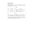
No.
Name
Quantity
1
Punch open support plate
1
2
Screw (bind, M4 x 6)
3
3
Punch unit
1
4
Punch unit fixing pin (for the finisher)
1
5
Punch unit fixing pin (for the saddle finisher)
1
6
Punch dust full sensor unit
1
7
Punch dust box
1
8
Card
1
9
Label 2
1
10
Screw (hex screw with flange, SRM4 x 8)
4
11
Step screw
1
12
Spring hook plate
1
13
Punch handle
1
14
Screw (TP, M3 x 6)
1
15
Screw (bind, M3 x 6)
1
1
2
3
4
5
6
7
8
9
10
11
12
13
14
15
MX-M1204 MX-PN13A/B/C/D (PUNCH MODULE) 19 – 2
2. Installation
NOTE: Installation must be executed in the sequence of the com-
plex machine body, the paper feed option, and the paper
exit option.
exit option.
NOTE: Before installation, be sure to turn both the operation and
main power switches off and disconnect the power plug
from the power outlet. Make double sure that the data lamp
on the operation panel does not light up or blink when per-
forming installation.
from the power outlet. Make double sure that the data lamp
on the operation panel does not light up or blink when per-
forming installation.
A. External fixture removal
1)
Open the front door of the finisher.
2)
Remove the inside upper cover.
In the case of the MX-FN21:
In the case of the MX-FN22:
3)
Use a nipper to cut out the dust-box blind cover of the inside
upper cover.
upper cover.
4)
Remove the rear cover of the finisher.
5)
Remove the rear cabinet of the finisher.
B. Transport unit removal
1)
Remove the earth, the connector, and the screw, and remove
the transport unit.
the transport unit.

