Sharp MX-6500N / MX-7500N (serv.man20) Service Manual ▷ View online
MX-7500N SIMULATION 6 – 125
61-4
Purpose
Adjustment
Function (Purpose)
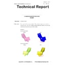
Used to print the print image skew adjust-
ment pattern. (LSU unit)
Section
Operation/Procedure
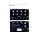
1) Select a target item with scroll key on the touch panel.
2) Enter the print conditions setting value with 10-key.
3) Press [EXECUTE] key.
1) Select a target item with scroll key on the touch panel.
2) Enter the print conditions setting value with 10-key.
3) Press [EXECUTE] key.
The print image skew adjustment pattern is printed.
61-11
Purpose
Adjustment
Function (Purpose)
Used to correct the laser power automati-
cally.
Section
Operation/Procedure
1) Select a target item with touch panel key.
1) Select a target item with touch panel key.
2) Press [AUTO CORRECTION] key.
3) Select the adjustment density pattern.
4) Press [EXECUTE] key.
5) The adjustment pattern is printed out.
6) Place the printed adjustment pattern on the document table
3) Select the adjustment density pattern.
4) Press [EXECUTE] key.
5) The adjustment pattern is printed out.
6) Place the printed adjustment pattern on the document table
(A4R direction), and press [EXECUTE] key.
The automatic correction of the laser power is performed, and
The automatic correction of the laser power is performed, and
then the adjustment result pattern is outputted.
7) To perform the correction again, press [RETRY] key.
8) When [DATA] key is pressed on the initial screen, the display is
8) When [DATA] key is pressed on the initial screen, the display is
shifted to the automatic adjustment result display screen.
61-12
Purpose
Adjustment
Function (Purpose)
Laser power manual correction
Section
Operation/Procedure
Press an item button to be adjusted.
When [MEASURING INSTRUMENT] is pressed:
1) Select the adjustment density pattern.
2) Press [EXECUTE] key.
3) The adjustment pattern is printed out.
4) Enter the adjustment value by the density meter.
5) Press [EXECUTE] key.
Press an item button to be adjusted.
When [MEASURING INSTRUMENT] is pressed:
1) Select the adjustment density pattern.
2) Press [EXECUTE] key.
3) The adjustment pattern is printed out.
4) Enter the adjustment value by the density meter.
5) Press [EXECUTE] key.
Execute the manual correction of the laser power. Then the
adjustment result pattern is outputted and the data are dis-
played.
6) To perform the correction again, press [RETRY] key.
When [VISUAL INSPECTION] is pressed:
1) Select the adjustment density pattern.
2) Press [EXECUTE] key.
3) The adjustment pattern is printed out.
4) Press [4POINT CORRECTION] or [31POINT CORRECTION].
5) Enter an adjustment value.
6) Press [EXECUTE] key.
When [VISUAL INSPECTION] is pressed:
1) Select the adjustment density pattern.
2) Press [EXECUTE] key.
3) The adjustment pattern is printed out.
4) Press [4POINT CORRECTION] or [31POINT CORRECTION].
5) Enter an adjustment value.
6) Press [EXECUTE] key.
Execute the manual correction of the laser power. Then the
adjustment result pattern is outputted and the data are dis-
played.
7) To perform the correction again, press [RETRY] key.
When [DATA] is pressed:
The display is shifted to the manual adjustment result display
When [DATA] is pressed:
The display is shifted to the manual adjustment result display
screen.
*: Since a special tool is required for measurement, this simulation
is executed only in the factory.
61-13
Purpose
Adjustment
Function (Purpose)
Used to clear the laser power correction
value.
Section
Operation/Procedure
1) Press [EXECUTE] key.
2) Press [YES] key.
1) Press [EXECUTE] key.
2) Press [YES] key.
Item/Display
Content
Setting
range
Default
value
A K_SKEW
Skew Motor Adjustment K
1 - 50(dot)
25
B C_SKEW
Skew Motor Adjustment C
1 - 50(dot)
25
C M_SKEW
Skew Motor Adjustment M
1 - 50(dot)
25
D Y_SKEW
Skew Motor Adjustment Y
1 - 50(dot)
25
E
OFFSET_SKEW_K
Skew Offset value K
1 - 50(dot)
25
F
OFFSET_SKEW_C
Skew Offset value C
1 - 50(dot)
25
G
OFFSET_SKEW_M
Skew Offset value M
1 - 50(dot)
25
H
OFFSET_SKEW_Y
Skew Offset value Y
1 - 50(dot)
25
I MULTI COUNT
Number of print
1 - 999
1
J PAPER
MFT
Tray
selection
Manual
paper feed
1 - 5
1
4(CS3)
CS1
Tray 1
2
CS2
Tray 2
3
CS3
Tray 3
4
CS4
Tray 4
5
K DUPLEX
YES
DUPLEX
YES
0 - 1
0
1(NO)
NO
NO
1
Items
Contents
Outline
AUTO
CORRECTION
Automatic correction
Adjustment by scanner
DATA
Data display screen
Data display when
executing the automatic
correction
Items
Contents
Outline
MEASURING
INSTRUMENT
Density meter correction *
Adjustment with the
density meter.
VISUAL
INSPECTION
Visual check adjustment
Adjustment by visual
check
DATA
Data display screen
Data display during
execution of the manual
correction
Reference value reset item
Laser power automatic correction amount (K) 32 data (point)
Laser power automatic correction amount (C) 32 data (point)
Laser power automatic correction amount (M) 32 data (point)
Laser power automatic correction amount (Y) 32 data (point)
Laser power manual correction amount (K) 32 data (point)
Laser power manual correction amount (C) 32 data (point)
Laser power manual correction amount (M) 32 data (point)
Laser power manual correction amount (Y) 32 data (point)
MX-7500N SIMULATION 6 – 126
62
62-1
Purpose
Data clear
Function (Purpose)
Used to format the hard disk/SD Card.
(HDD: Excluding the Operation manual and
the watermark data) (SD Card: User data)
Section
Operation/Procedure
1) Press [EXECUTE] key.
2) Press [YES] key.
1) Press [EXECUTE] key.
2) Press [YES] key.
Used to execute the HDD/SD Card format.
When the operation is completed, [EXECUTE] key returns to the
normal display.
62-2
Purpose
Operation test/check
Function (Purpose)
Used to check read/write of the hard disk
(partial).
Section
Operation/Procedure
1) Press [EXECUTE] key.
2) Press [YES] key.
1) Press [EXECUTE] key.
2) Press [YES] key.
62-3
Purpose
Operation test/check
Function (Purpose)
Used to check read/write of the hard disk
(all areas).
Section
Operation/Procedure
1) Press [EXECUTE] key.
2) Press [YES] key.
1) Press [EXECUTE] key.
2) Press [YES] key.
Read/write operations are performed.
62-6
Purpose
Operation test/check
Function (Purpose)
Used to perform the self diagnostics of the
hard disk.
Section
Operation/Procedure
1) Select the self diag area.
2) Press [EXECUTE] key.
1) Select the self diag area.
2) Press [EXECUTE] key.
The self diag operation is performed.
NOTE: E7-03 error occurs. If there may be a trouble in the HDD,
use this simulation to cheek the HDD.
When the operation is completed, [EXECUTE] key returns to the
normal display.
Normal completion - "OK (RESULT:0)" is displayed.
Normal completion - "OK (RESULT:0)" is displayed.
Abnormal end - "NG (RESULT: Other than 0)" is displayed.
* If the simulation cannot be executed or terminated abnormally for
* If the simulation cannot be executed or terminated abnormally for
some reason, "ERROR" is displayed on the corresponding sec-
tion.
62-7
Purpose
Operation test/check
Function (Purpose)
Used to print the hard disk self diagnostics
error log.
Section
Operation/Procedure
1) Press [EXECUTE] key.
ERROR LOG SECTOR of the SMART function is executed, and
1) Press [EXECUTE] key.
ERROR LOG SECTOR of the SMART function is executed, and
the result is printed.
When the operation is completed, [EXECUTE] key returns to the
When the operation is completed, [EXECUTE] key returns to the
normal display.
62-8
Purpose
Data clear
Function (Purpose)
Used to format the hard disk/SD Card.
(HDD: Excluding the Operation Manual, the
watermark data, and the system area) (SD
Card: User data)
Section
Operation/Procedure
1) Press [EXECUTE] key.
2) Press [YES] key.
1) Press [EXECUTE] key.
2) Press [YES] key.
Used to execute the hard disk format.
When the operation is completed, [EXECUTE] key returns to the
normal display.
* When the HDD formatting (except for the system area) is not
* When the HDD formatting (except for the system area) is not
completed normally, "HDD FORMAT (EXCEPT SYSTEM AREA)
NG" is displayed.
62-10
Purpose
Data clear
Function (Purpose)
Used to clear the job completion list data.
Section
Operation/Procedure
1) Press [EXECUTE] key.
2) Press [YES] key.
1) Press [EXECUTE] key.
2) Press [YES] key.
Used to delete the job log data.
When the operation is completed, [EXECUTE] key returns to the
normal display.
62-11
Purpose
Data clear
Function (Purpose)
Used to delete the document filing data.
Section
Operation/Procedure
1) Press [EXECUTE] key.
2) Press [YES] key.
1) Press [EXECUTE] key.
2) Press [YES] key.
Used to delete the document filing data.
When the operation is completed, [EXECUTE] key returns to the
normal display.
SHORT S.T
Partial area diag
EXTENDED S.T
All area diag
MX-7500N SIMULATION 6 – 127
62-12
Purpose
Setting
Function (Purpose)
Used to set Enable/Disable of auto format
in a hard disk trouble.
Section
Operation/Procedure
1) Enter the set value with 10-key.
2) Press [OK] key.
1) Enter the set value with 10-key.
2) Press [OK] key.
The set value is saved.
data storage area is cleared.
62-13
Purpose
Data clear
Function (Purpose)
Used to format the hard disk. (Operation
Manual, watermark data only)
Section
Operation/Procedure
1) Press [EXECUTE] key.
2) Press [YES] key.
1) Press [EXECUTE] key.
2) Press [YES] key.
The operation manual data are deleted.
When the operation is completed, [EXECUTE] key returns to the
normal display.
62-14
Purpose
Data clear
Function (Purpose)
Used to delete the document filing manage-
ment data.
Section
HDD
Operation/Procedure
1) Press [EXECUTE] key.
2) Press [YES] key.
1) Press [EXECUTE] key.
2) Press [YES] key.
The document filing management data are cleared.
At the same time, the job log data are also cleared.
At the same time, the job log data are also cleared.
This simulation is executed in the following trouble cases.
* The document filing function does not work normally.
* The job log is not recorded normally.
NOTE:
This simulation may not function with some firmware versions.
In such a case, the firmware must be upgraded to the latest ver-
* The document filing function does not work normally.
* The job log is not recorded normally.
NOTE:
This simulation may not function with some firmware versions.
In such a case, the firmware must be upgraded to the latest ver-
sion.
62-20
Purpose
Operation test/check
Function (Purpose)
Used to check the operation of the mirror-
ing hard disk.
Section
Mirroring hard disk
Operation/Procedure
Enter the simulation mode, and the operation status of the HDD is
Enter the simulation mode, and the operation status of the HDD is
displayed.
The status display is renewed in every second.
The status display is renewed in every second.
63
63-1
Purpose
Adjustment/Setting/Operation data check
Function (Purpose)
Used to display the shading correction
result.
Section
Scanner
Operation/Procedure
1) Select a target color to display with [R] [G] [B] on the touch
1) Select a target color to display with [R] [G] [B] on the touch
panel.
Item
Content
Default value
A
0
Enable
1
1
Disable
Display
Content description
OK
Normal operation
NONE
Not connected
REBUILDING
Data rebuilding
ERROR
Error occurrence
TROUBLE
Trouble
Button
Display
item
Description
Remarks
OC
ANALOG
GAIN ODD
Analog gain
adjustment value
(odd number)
ANALOG
GAIN
EVEN
Analog gain
adjustment value
(even number)
DIGITAL
GAIN ODD
Digital gain
adjustment value
(odd number)
DIGITAL
GAIN
EVEN
Digital gain
adjustment value
(even number)
SMP AVE
ODD
Reference plate
sampling average
value (odd number)
SMP AVE
EVEN
Reference plate
sampling average
value (even number)
TARGET
VALUE
Target value
BLACK
LEVEL
Black output level
ERROR
CODE
Error code (0, 1 - 14)
0: No error
1: STAGE1. Loop
1: STAGE1. Loop
number over
2: STAGE2. The
target value is less
than the specified
level.
3: STAGE3. The gain
set value is
negative.
4: END is not
asserted. (Gain
adjustment)
5: (reserve)
6: STAGE2.
6: STAGE2.
Underflow
MX-7500N SIMULATION 6 – 128
63-2
Purpose
Adjustment
Function (Purpose)
Used to perform shading.
Section
Operation/Procedure
- DSPF-installed model
1) Select [OC SHADING] key or [DSPF SHADING] key, and
- DSPF-installed model
1) Select [OC SHADING] key or [DSPF SHADING] key, and
press [EXECUTE] key.
Used to perform shading.
Used to perform shading.
When the operation is completed, [EXECUTE] key returns to the
normal display.
63-3
Purpose
Adjustment
Function (Purpose)
Used to perform scanner (CCD) color bal-
ance and gamma auto adjustment.
Section
Scanner
Operation/Procedure
1) Place the SIT chart (UKOG-0280FCZZ or UKOG-0280FCZ1)
1) Place the SIT chart (UKOG-0280FCZZ or UKOG-0280FCZ1)
on the reference position of the left rear frame side of the doc-
ument table. For the DSPF mode, put the SIT chart backside
up on the DSPF tray.
2) Select [OC] key or [DSPF] key.
3) Press [EXECUTE] key.
3) Press [EXECUTE] key.
The scanner (CCD) color balance automatic adjustment is per-
formed.
When the operation is completed, [EXECUTE] key returns to the
normal display.
After completion of the operation, press [RESULT] key, and the
After completion of the operation, press [RESULT] key, and the
adjustment data are displayed. At that time, the target color of data
display can be selected with [R] [G] [B] key.
OC
ERROR
CODE
Error code (0, 1 - 14)
7: Black shading error
8: Other error
9: END is not
8: Other error
9: END is not
asserted. (White
shading)
10: END is not
asserted. (Black
shading)
11: END is not
asserted. (Light
quantity correction)
12: END is not
asserted. (Scan)
13: Register check
error (When
starting/Gain)
14: Register check
error (Before light
quantity correction)
DSPF
FACE
WHITE
LEVEL 1ST
First scan DSPF
front surface white
reference level
DSPF
FACE
WHITE
LEVEL 2ND
Second scan DSPF
front surface white
reference level
DSPF
ANALOG
GAIN ODD
Analog gain
adjustment value
(odd number)
ANALOG
GAIN
EVEN
Analog gain
adjustment value
(even number)
DIGITAL
GAIN ODD
Digital gain
adjustment value
(odd number)
DIGITAL
GAIN
EVEN
Digital gain
adjustment value
(even number)
SMP AVE
ODD
Reference plate
sampling average
value (odd number)
SMP AVE
EVEN
Reference plate
sampling average
value (even number)
TARGET
VALUE
Target value
BLACK
LEVEL
Black output level
ERROR
CODE
Error code (0, 1 - 14)
0: No error
1: STAGE1. Loop
1: STAGE1. Loop
number over
2: STAGE2. The
target value is less
than the specified
level.
3: STAGE3. The gain
set value is
negative.
4: END is not
asserted. (Gain
adjustment)
5: (reserve)
6: STAGE2.
6: STAGE2.
Underflow
7: Black shading error
8: Other error
9: END is not
8: Other error
9: END is not
asserted. (White
shading)
10: END is not
asserted. (Black
shading)
Button
Display
item
Description
Remarks
DSPF
ERROR
CODE
Error code (0, 1 - 14) 11: END is not
asserted. (Light
quantity correction)
12: END is not
asserted. (Scan)
13: Register check
error (When
starting/Gain)
14: Register check
error (Before light
quantity correction)
DSPF
BACK
WHITE
LEVEL 1ST
First scan DSPF
back surface white
reference level
DSPF
BACK
WHITE
LEVEL 2ND
Second scan DSPF
back surface white
reference level
Button
Display
item
Description
Remarks


