Sharp 66FW-54H (serv.man7) Service Manual ▷ View online
50Hz
Colour Television
DA100 and DW100
Chassis
Colour Television – DA100/DW100 Chassis
Sharp Electronics (UK) Ltd
Technical Support
September 99
Contents
POWER SUPPLIES...........................................................................................................................1
Switch Mode Power Supply......................................................................................................1
Start up operation...........................................................................................................1
Voltage regulation ..........................................................................................................2
Over-voltage Protection..................................................................................................2
Over-current control .......................................................................................................2
Slave Processor Power Supply.................................................................................................3
Degauss Circuit........................................................................................................................4
5v Regulator ............................................................................................................................5
Degauss Circuit........................................................................................................................4
5v Regulator ............................................................................................................................5
DA100 (59ESD7H and 66ESD7H) 4:3 chassis................................................................5
DW100 (56FW53H to 6FW54H) 16:9 chassis .................................................................6
DW100 (56FW53H to 6FW54H) 16:9 chassis .................................................................6
CLASS D OUTPUT STAGES ............................................................................................................7
Tda7480 Pin Functions.............................................................................................................7
Pin 9 – Frequency ..........................................................................................................7
Pin 12 – Mute/Standby function ......................................................................................7
Pin 12 – Mute/Standby function ......................................................................................7
Audio Output............................................................................................................................8
Field Output .............................................................................................................................9
Field Output .............................................................................................................................9
Vertical Fly-back...........................................................................................................10
VIDEO AND SYNC PROCESSOR ...................................................................................................11
Description.............................................................................................................................11
Analogue front-end.......................................................................................................11
Input Selector ...............................................................................................................11
Clamping......................................................................................................................11
Automatic Gain Control ................................................................................................12
Analogue-to-Digital Converters.....................................................................................12
Digitally Controlled Clock Oscillator ..............................................................................12
Analogue Video Output ................................................................................................12
Average Beam Current Limiting....................................................................................12
Protection Circuitry .......................................................................................................12
Scan Velocity Modulation Output ..................................................................................12
PICTURE ROTATION......................................................................................................................13
SCAN VELOCITY MODULATOR ....................................................................................................14
LINE OUTPUT STAGE....................................................................................................................15
East West Circuit....................................................................................................................16
Circuit Description ........................................................................................................16
MICROPROCESSOR CONTROL ....................................................................................................17
Reset .....................................................................................................................................18
PROTECTION .................................................................................................................................19
Microprocessor.......................................................................................................................19
Audio Output ................................................................................................................19
Beam Current...............................................................................................................19
Horizontal Mute ............................................................................................................19
Beam Current...............................................................................................................19
Horizontal Mute ............................................................................................................19
Video/Sync Processor ............................................................................................................20
Safety ..........................................................................................................................20
Vprot ............................................................................................................................20
Vprot ............................................................................................................................20
Colour Television – DA100/DW100 Chassis
Sharp Electronics (UK) Ltd
Technical Support
September 99
Page 1
POWER SUPPLIES
This CTV employs two power supplies, which are similar in design to previous models. The Power
Supply located on the sub-board 'PWB-C' will supply the Dolby Prologic circuit and Audio Output
Stages that are also located on PWB-C. Similar to the CS, CA10 and CW100 chassis, when this
receiver is in standby mode, the outputs from the power supplies (including the supply to the Main
Microprocessor circuit) will be muted by removal of the FET gate voltage. The Slave Processor
(IC702) performs standby and timer on/off functions, additionally in this chassis the Slave Processor
will control the degauss circuit.
S
WITCH
M
ODE
P
OWER
S
UPPLY
S
TART UP OPERATION
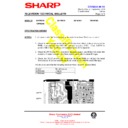
Rectified and smoothed mains voltage (+320VDC) is used to provide the start up voltage to the gate
of Q701. Current flows via R713 and R714 charging C714 (C714 earth return is via T701 secondary
winding pins 14 and 15). This allows a voltage at the gate of Q701 to rise slowly (Q701 will turn on
when the gate reaches 4.5V). D712 ensures that Q701 gate voltage will not exceed 15V, preventing
the FET being damage by voltage spikes.
When Q701 turns on, current will flow from the bridge rectifier, through T701 primary winding (pins 12
and 17), Q701 source/drain junction, returning to the bridge rectifier via, R716. The current flowing
through T701 primary will induce an e.m.f. into secondary windings
and 17), Q701 source/drain junction, returning to the bridge rectifier via, R716. The current flowing
through T701 primary will induce an e.m.f. into secondary windings
The e.m.f. produced at T701 pin 15 will flow through D715 and the collector emitter junction of the
opto-coupler (IC705), charging C713. Once the charge on C713 reaches 0.6V Q703 will turn on,
connecting Q701 gate to ground, turning Q701 off and discharging C714.
opto-coupler (IC705), charging C713. Once the charge on C713 reaches 0.6V Q703 will turn on,
connecting Q701 gate to ground, turning Q701 off and discharging C714.
R713
560k
560k
R714
560k
560k
Q701
C712
100pF
100pF
Standby
D730
Q702
Q703
D713
R719
220
220
R717
22k
22k
R716
0R47
0R47
C713
68nF
68nF
C711
330pF
330pF
C714
82nF
82nF
D711
C710
47nF
47nF
T701
17
12
R730
82
82
C715
330pF
330pF
D716
5v6
5v6
D715
R722
0R33
0R33
R723
270
270
C717
15nF
15nF
C718
3n3
3n3
IC705
2
1
15
14
6
5
4
D720
C720
100
100
150V
-16v
3
7
D719
C719
1000
1000
8
D718
C718
1000
1000
+16v
D712
15v
15v
+8v
D721
8v2
8v2
R727
180
180
R728
180
180
R715
47k
47k
R718
18
18
C738
56pF
56pF
To Degauss
Circuit
Circuit
+HT
R766
220
220
R765
220
220
D726
12v
12v
R743
47k
47k
R744
47k
47k
R746
47k
47k
R724
470
470
R750
1M
1M
IC706
R745
1k8
1k8

