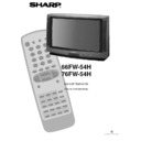
Sharp 66FW-54H (serv.man30) Service Manual / Technical Bulletin ▷ View online
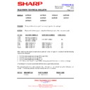
CTV2002 05 02
Month of Issue:
October 2002
Classification:
White
TELEVISION TECHNICAL BULLETIN
Page 1 of 3
Sharp Electronics (UK) Limited
Reference JR21052002-1
Revision 3
White – Carry out as required
Yellow – Carry out as required and whenever the unit comes in for service
Red – Carry out on all units
MODELS
56FW53H
66FW53H
76FW53H
66FW54H
76FW54H
66GF63H
66GF64H
76GF64H
28HW53H
32HW53H
REASON
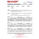
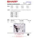
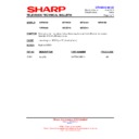
Change of the opto coupler from a six-pin type to a four-pin type.
ACTION
Replace the following parts noting the different pin outs of the new opto coupler.
REF NO
OLD PART NUMBER
NEW PART NUMBER
PRICE CODE
IC705
IC703
IC704
IC1703
IC703
IC704
IC1703
RH-FX0106BMZZ or
RH-FX0110BMZZ or
RH-FX0112BMZZ
RH-FX0110BMZZ or
RH-FX0112BMZZ
RH-FX0113BMZZ
AD
R724
VRS-TQ2BD271J
VRS-TQ2BD221J
AA
R750
VRS-TV1JD104J
VRS-TV1JD334J
AA
R711
VRS-TV1JD182J
VRS-TV1JD122J
AA
R1017
VRS-TV1JD122J
VRS-TV1JD102J
AA
When replacing the original six-pin opto coupler with a four-pin type, it is important that the following
resistors are changed:
resistors are changed:
•
If IC705 is being replaced, change R724 and R750
•
If IC703 is being replaced, change R711
•
If IC704 is being replaced, change R1017
•
If IC1703 (on the Dolby Pro-Logic PWB) is being replaced, there are no resistors to change
Only change the resistors associated with the opto coupler being replaced.
The required parts have been prepared into a kit and can be ordered using the following part
number. This kit only contains one opto coupler and all the resistors.
number. This kit only contains one opto coupler and all the resistors.
REF NO
DESCRIPTION
PART NUMBER
PRICE CODE
-
Parts kit
GF/FWOPTOKIT
AE
CTV2002 05 02
Month of Issue:
October 2002
Classification:
White
TELEVISION TECHNICAL BULLETIN
Page 2 of 3
Sharp Electronics (UK) Limited
Reference JR21052002-1
Revision 3
White – Carry out as required
Yellow – Carry out as required and whenever the unit comes in for service
Red – Carry out on all units
Notes
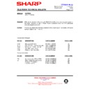
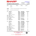
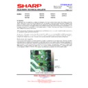
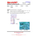
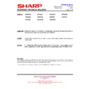
This is a four-pin device and replaces the original six-pin device.
Pins 1 and 2 of the new four-pin device are the same as the original six-pin IC. Pins 3 and 4 are the
equivalent of pins 4 and 5. See picture below for more detail:
Pins 1 and 2 of the new four-pin device are the same as the original six-pin IC. Pins 3 and 4 are the
equivalent of pins 4 and 5. See picture below for more detail:
Original Device
Replacement Device
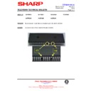
This requires that the new opto-coupler is fitted diagonally, so that the pins are correctly aligned.
Positioning of the opto couplers in the case of IC705 (power)
1
2
3
6
5
4
1
2
4
3
CTV2002 05 02
Month of Issue:
October 2002
Classification:
White
TELEVISION TECHNICAL BULLETIN
Page 3 of 3
Sharp Electronics (UK) Limited
Reference JR21052002-1
Revision 3
White – Carry out as required
Yellow – Carry out as required and whenever the unit comes in for service
Red – Carry out on all units
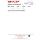
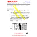
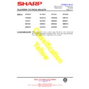
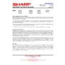
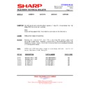
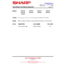
Postioning of the data opto couplers (IC703 and IC704)
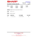
Positioning in the case of the Dolby Power supply (IC1703)
Display

