Sharp 66FW-54H (serv.man15) Service Manual / Technical Bulletin ▷ View online
CTV2003 06 01
Month of Issue: 18
th
August 2004
Classification:
White
TELEVISION TECHNICAL BULLETIN
Page 1 of 2
Sharp Electronics (UK) Limited
Reference AVW 06062003 - 1
Revision 4
White – Carry out as required
Yellow – Carry out as required and whenever the unit comes in for service
Red – Carry out on all units
MODELS
56FW53H
66FW53H
66FW54H
76FW53H
76FW54H
59ESD7H
66ESD7H
66GF63H
66GF64H
76GF63H
76GF64H
28HW53H
32HW53H
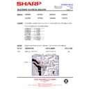
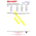
Faults in the East/West Circuit
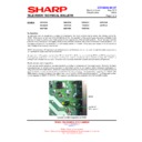
When fault finding in the east/west circuit, it is important to ascertain in which part of the circuit the fault lies. Check the
When fault finding in the east/west circuit, it is important to ascertain in which part of the circuit the fault lies. Check the
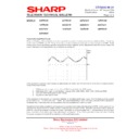
control output of IC801 – pin 32. There should be a parabola waveform on this pin at a base frequency of 50Hz. It will
change wave shape depending upon the amount of correction applied, so it is important to enter the service mode and
ensure that none of the adjustments are at minimum or maximum.
If this waveform is present, and changes as adjustments are made, then the fault will lie in the drive or output circuitry.
Faults in this area include:
1. R519 going high or open circuit – it is a 100k
Ω connected to the 150V supply.
2. Q506 going short, open or overheating – change L603, L604, D502, D503, D504, D516 and C528.
3. D603 and D604 going open or short-circuit.
4. Dry joint on C601 and/or C610.
If the waveform is not present, or is severely distorted, or the adjustment range is poor, then the fault could be caused
by the memory IC – IC1003 or the VDP - IC801. It is recommended that if this is the case, then the NVM is blanked or
re-flashed first. If this does not cure the problem, then it is probable that IC801 is at fault.
Sometimes it will not be possible to set the geometry correctly in all modes after blanking he NVM. In this case it will be
necessary to ensure that the EPROM (IC1002) is correct (see CTV2001 05 04). When the correct EPROM is fitted, the
NVM will have to be blanked to enable the correct information to be downloaded into it. Replacement EPROM’s have
been produced so that minimal geometry adjustments are required. If the picture geometry is very poor after following
the above procedure, the fault will be elsewhere in the east/west circuitry.
CTV2003 06 01
Month of Issue: 18
th
August 2004
Classification:
White
TELEVISION TECHNICAL BULLETIN
Page 2 of 2
Sharp Electronics (UK) Limited
Reference AVW 06062003 - 1
Revision 4
White – Carry out as required
Yellow – Carry out as required and whenever the unit comes in for service
Red – Carry out on all units
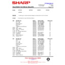
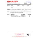
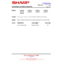
Reference Function
Part Number
Comment
C528
Reservoir capacitor
VCEAGA1JW106M
Leaky
D502/3/4
Clamping diodes
RH-DX0551BMZZ
Intermittently faulty
D516
Clamping diode
RH-EX0837BMZZ
Intermittently faulty
D603
East/west modulator diode
RH-DX0299BMZZ
Open or short circuit
D604
East/west modulator diode
RH-DX0302BMZZ
Open or short circuit
IC1003
NVM
RH0IX1603BMZZ
Corrupted - reprogram
IC801
VDP 3120C2
RH-IX1688BMN2
No output
IC801
VDP 3130Y
RH-IX1858BMZZ
No output
L603
Feed coil
RCILP0286BMZZ
See note below for DA50W models
L604
Line earth return coil
RCILP0284BMZZ
See note below for DA50W models
Q506
Eat/west output transistor
RH-TX0151BMZZ
Open or leaky – SMD
R519
Ramp charging resistor
VRD-RA2HD104J
Goes high or open – on component side of PWB
Notes
• The component list above shows the various component part numbers for parts mentioned in this Technical Bulletin
- it is not a list of components to change for east/west or geometry problems.
• IC801 can either be a 3120 or 3130 - please check before replacement.
• D516 is not shown on the GF circuit diagram, although it is fitted to the chassis.
• R519 is sometimes a 150kΩ resistor, check the value before replacing, as fitting the incorrect value will result in
poor east/west geometry performance.
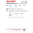
• L603 and L604 can differ in the DA50W chassis. Be careful to order the correct types from the list below:
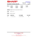
Model Number
L603 Part Number
L603 Type
L604 Part Number
L604 Type
66GF63H
RCILP0262BMZZ
P0262
RCILP0294BMZZ
P0294M
66GF64H
RCILP0262BMZZ
P0262
RCILP0294BMZZ
P0294M
76GF63H
RCILP0286BMZZ
P0286
RCILP0294BMZZ
P0294BM
76GF64H
RCILP0286BMZZ
P0286
RCILP0284BMZZ
P0284BM
Display

