Sharp 66FW-54H (serv.man21) Service Manual / Technical Bulletin ▷ View online
CTV2003 04 12
Month of Issue:
May 2003
Classification:
White
TELEVISION TECHNICAL BULLETIN
Page 1 of 3
Sharp Electronics (UK) Limited
Reference JR29042003-8
Revision 2
White – Carry out as required
Yellow – Carry out as required and whenever the unit comes in for service
Red – Carry out on all units
MODELS
56FW53H
66FW53H
66FW54H
76FW53H
76FW54H
59ESD7H
66ESD7H
28HW53H
66GF63H
66GF64H
76GF64H
SYMPTOM
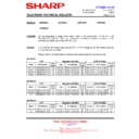
In some cases the HT can rise to over 200V, this can cause damage to other parts of the circuitry
CAUSE
Failure of IC705 - power supply feedback opto coupler.
ACTION
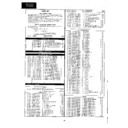
In most cases, when the HT rises D735 fails and no other components are damaged. Replace D735
and IC705 using the part numbers listed below. (D735 may be soldered under C720)
and IC705 using the part numbers listed below. (D735 may be soldered under C720)
If after the above the set remains in trip mode, other components may have failed, the table below gives
details.
details.
Ref
Function
Part Number
Comment
Q602
Horizontal output transistor
RH-TX0192BMZZ
Leaky or short circuit
IC301/2
Audio output IC’s
VHITDA7480/-1
Short circuit. Also check supply feed chokes
IC1801
CDA IC on CRT base PWB
Refer to service manual
Short circuit. Check pin 5 to ground (<500
Ω
)
C720
HT reservoir capacitor
RC-EZ0258CEZZ
Physically damaged
IC1301
Centre channel amplifier
VHITDA7480/-1
Short circuit. Located on centre speaker PWB
Q5407
Scan velocity modulator transistor
VS2SA1837//-1
CRT PWB – short or open circuit
Q5408
Scan velocity modulator transistor
VS2SC4793//-1
CRT PWB – short or open circuit
L315/316
IC302 feed chokes
VP-CF3R3K0000
Open circuit
L350/351
IC301 feed chokes
VP-CF3R3K0000
Open circuit
The opto coupler is easily damaged by excessive heat while soldering, so remember to keep your
soldering iron temperature turned down to 250
soldering iron temperature turned down to 250
o
C or below, and not to solder for more than 10 seconds
on each leg. If these conditions are not met the transparent barrier between the LED and opto
transistor will be damaged. Note that sometimes the set will work for several weeks or months before
failing if the opto has been damaged during fitting.
transistor will be damaged. Note that sometimes the set will work for several weeks or months before
failing if the opto has been damaged during fitting.
To alleviate damage to other parts of the circuitry when the HT rises, an avalanche diode was fitted
across the main HT smoothing capacitor (C720) from late 1999 production. This device has a rated
maximum voltage of 170V, and will go short circuit if this voltage is reached. This diode must be fitted
to all chassis (part number RH-EX0875BMZZ).
across the main HT smoothing capacitor (C720) from late 1999 production. This device has a rated
maximum voltage of 170V, and will go short circuit if this voltage is reached. This diode must be fitted
to all chassis (part number RH-EX0875BMZZ).
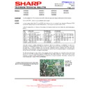
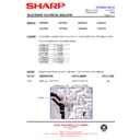
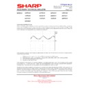
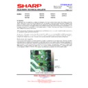
Location of D735 (note the use of hot melt
glue to prevent the diode from shorting out
to the tracking)
CTV2003 04 12
Month of Issue:
May 2003
Classification:
White
TELEVISION TECHNICAL BULLETIN
Page 2 of 3
Sharp Electronics (UK) Limited
Reference JR29042003-8
Revision 2
White – Carry out as required
Yellow – Carry out as required and whenever the unit comes in for service
Red – Carry out on all units
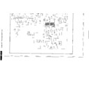
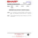
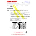
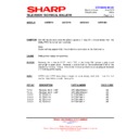
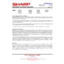
Location of Audio Stage components (Main PWB)
Location of Centre Speaker PWB
CTV2003 04 12
Month of Issue:
May 2003
Classification:
White
TELEVISION TECHNICAL BULLETIN
Page 3 of 3
Sharp Electronics (UK) Limited
Reference JR29042003-8
Revision 2
White – Carry out as required
Yellow – Carry out as required and whenever the unit comes in for service
Red – Carry out on all units
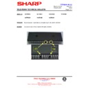
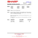
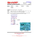
Location of Components on the CRT PWB - 66cm and 76cm versions only (the PWB fitted to the 56FW53H does
not have Q5407/Q5408 fitted and is phyusically smaller then this example)
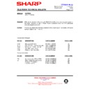
When the avalanche diode is fitted, only four components generally need to be replaced (D735, Q601,
IC705 and C720), this is because it prevents further damage to the circuitry should the power supply be
kept running. Sharp produce a kit that contains these four items - use the part number
FWSERVKIT01//
IC705 and C720), this is because it prevents further damage to the circuitry should the power supply be
kept running. Sharp produce a kit that contains these four items - use the part number
FWSERVKIT01//
REF NO
DESCRIPTION
PART NUMBER
PRICE CODE
---
FW Kit 01
FW SERVKIT01//
AR
NOTES:
•
When
replacing
any opto coupler ensure that the soldering temperature is below 250
°°°°
C.
•
To ensure that excessive HT does not cause further problems, if not previously fitted make sure that an avalanche
diode (D735) is fitted across C720 on the print side of the PWB. The cathode of the diode should be connected to
the positive side of C720.
diode (D735) is fitted across C720 on the print side of the PWB. The cathode of the diode should be connected to
the positive side of C720.
•
Display

