Sharp 66FW-54H (serv.man22) Service Manual / Technical Bulletin ▷ View online
CTV2003 04 13
Month of Issue:
May 2003
Classification:
White
TELEVISION TECHNICAL BULLETIN
Page 1 of 2
Sharp Electronics (UK) Limited
Reference JR29042003-9
Revision 2
White – Carry out as required
Yellow – Carry out as required and whenever the unit comes in for service
Red – Carry out on all units
MODELS
56FW53H
66FW53H
66FW54H
76FW53H
76FW54H
59ESD7H
66ESD7H
66GF63H
66GF64H
76GF64H
28HW53H
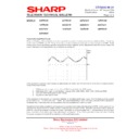
Vertical Collapse and Distortion Problems
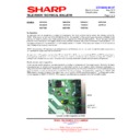
Most vertical faults can be traced to either software corruption or output IC failure. If the NVM corrupts, then it can
cause severe vertical distortion, no drive or fold-over at the top of the screen. An NVM problem can be eliminated from
the fault-finding procedure by reflashing.
Most vertical faults can be traced to either software corruption or output IC failure. If the NVM corrupts, then it can
cause severe vertical distortion, no drive or fold-over at the top of the screen. An NVM problem can be eliminated from
the fault-finding procedure by reflashing.
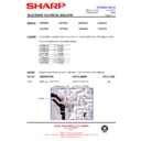
If you have a severe vertical distortion problem, or a very small picture, it is possible that the mute pin (pin 12) is not
+5V. At any voltage less than 2.7V, the output of the IC will be attenuated by 70dB, therefore if C511 or R509 fail, the
above symptoms with be noted.
+5V. At any voltage less than 2.7V, the output of the IC will be attenuated by 70dB, therefore if C511 or R509 fail, the
above symptoms with be noted.
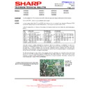
Foldover at the bottom of the screen after about fifteen minutes operation can be caused by SMD capacitor C505
(100nF). Replace it with Sharp part number VCKYTV1HF104Z.
(100nF). Replace it with Sharp part number VCKYTV1HF104Z.
For vertical collapse, reduced vertical scan or East / West circuits components failing (Q506 etc) change C632.
Lines at the top of the picture
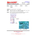
Sometimes red, green and blue lines can be seen at the top of the screen. This normally means that the automatic
grey-scaling lines (generated during the vertical fly-back period) are not being blanked correctly. Adjustment of the G2
setting on the horizontal output transformer will normally cure this problem. However, it is possible for this fault to be
generated by mis-operation of the vertical fly-back circuit. First check that the +25V supply generated by D510/C520 is
not low (below +18V), and there is no excessive ripple. If there is a problem in this area, the fly-back circuit is unable to
generate enough of a pulse to send the spot back to the top of the screen. It is not unusual to find that either C520 or
R530 (feed resistor) to be faulty in some way.
In the case of the 56FW53H fitted with a Thomson CRT, ensure that the NVM location F7 on page 0C is OD. This
location controls the vertical blanking point and if set incorrectly can cause red, blue and green lines to flash
intermittently at the top of the screen. This location can be incremented to 0E, 0F or 10 if necessary. 10 is the
maximum value allowable, as any setting greater than this will cause the blanking level to become unstable. If the fault
persists with a setting of 10, there is a fault elsewhere on the chassis.
Blank raster
You may experience a blank picture fault symptom that has been caused by a fault in the vertical stage. To alleviate
any problems should there be a vertical collapse, i.e. a line burnt onto the CRT face, IC801 monitors the vertical fly-
back pulse. If this is missing, IC801 will blank the picture by shutting down its RGB output. When fault finding this fault
condition, it is advisable to check the PROT pin of IC801 (pin 11). This should have a 50Hz pulse at 5V amplitude
applied to it. If there is a problem in the fly-back circuit, this pulse is not generated, or may be corrupted, and IC801
cuts off the RGB drive to the CRT base panel. Normally Q502 and/or Q503 being leaky or short circuit causes this
fault. In most cases the +25V line is also low.
CTV2003 04 13
Month of Issue:
May 2003
Classification:
White
TELEVISION TECHNICAL BULLETIN
Page 2 of 2
Sharp Electronics (UK) Limited
Reference JR29042003-9
Revision 2
White – Carry out as required
Yellow – Carry out as required and whenever the unit comes in for service
Red – Carry out on all units
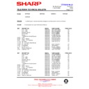
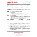
REF NO
DESCRIPTION
PART NUMBER
PRICE CODE
C505
Capacitor, 100nF 50V
VCKYTV1HF104Z
AA
C511
Capacitor, 2.2
µ
F 50V
VCEAGA1HW225M
AB
C520
Capacitor, 470
µ
F 35V
VCEAGA1VW477M
AC
C632
Capacitor, 470
µ
F, 35V
VCEAGA1EW477M
AD
D510
Diode, 1N4935
RH-DX0505BMZZ
AE
IC501
IC, TDA7480
RH-IX1786BMZZ
AL
Q502
Transistor, KSA928A
RH-TX0201BMZZ
AC
Q503
Transistor, IRFR010TM
RH-TX0172BMZZ
AE
R509
Resistor, 39k
Ω
1/10W
VRS-TV1JD393J
AA
R530
Resistor, 10
Ω
fusible
RR-XZ0212BMZZ
AB
Note
The vertical output IC is the same as that used in the audio stage, so substituting the IC will prove if it is faulty.
The vertical output IC is the same as that used in the audio stage, so substituting the IC will prove if it is faulty.
Display

