Sharp 66FW-54H (serv.man19) Service Manual / Technical Bulletin ▷ View online
CTV2002 01 04
Month of Issue:
May 2003
Classification:
White
TELEVISION TECHNICAL BULLETIN
Page 1 of 2
Sharp Electronics (UK) Limited
Reference JR07012002-1
Revision 3
White – Carry out as required
Yellow – Carry out as required and whenever the unit comes in for service
Red – Carry out on all units
MODELS
56FW53H
66FW53H
76FW53H
66FW54H
76FW54H
28HW53H
66GF63H
66GF64H
76GF64H
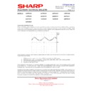
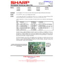
Horizontal Output Transistor Failure
If the negative supply used to turn off the horizontal output transistor is too low, then it will not turn off fully. This will
result in a large voltage across the collector/emitter junction and current being drawn at the same time. The power
generated will have to be dissipated by the transistor itself and therefore it will get very hot. Eventually it will fail. A
cause of this is failure of C607 (low capacity or leaky), causing the negative supply to fall. Note that it is advisable to
change this for a 105
o
C device if it has not already been done.
For intermittent failure of the horizontal output transistor it is recommended that C607, D610 and D611 be replaced.
Dry joints in the output stage can also cause this problem – the most common areas affected are the horizontal coil
earth return circuit C613, R613 and associated circuitry and the scan coil connector itself. Sometimes C613 and/or
R613 will go open circuit resulting in no horizontal scan leading to the possibility of the horizontal output transistor going
short or leaky. C613 can also go faulty under load, so it is best to check by substitution. C528, C632 and C615 are
also known to cause the output transistor to fail intermittently.
The opto coupler feedback IC, IC705 can cause the HT to rise slowly. This results in Q601 failing before the avalanche
diode goes short circuit. This can take up to several hours to happen.
diode goes short circuit. This can take up to several hours to happen.
Note that the horizontal output transistor must be the correct type. Failure to use the correct transistor will result in
erratic operation or premature failure of the device.
erratic operation or premature failure of the device.
Partial or Complete Line Collapse/Intermittent Operation
Clean and resolder legs on C613. In severe cases arcing from the joint may have caused failure of R610, R613 and
L603 in addition to the transistors Q601 and Q506. If Q506 runs very hot when replaced L603 must be changed.
Clean and resolder legs on C613. In severe cases arcing from the joint may have caused failure of R610, R613 and
L603 in addition to the transistors Q601 and Q506. If Q506 runs very hot when replaced L603 must be changed.
Large Picture
If D1601 on the focus modulator PWB (76cm models only), goes leaky or short circuit, the result is an over large picture
due to the EHT dropping to about 20kV.
If D1601 on the focus modulator PWB (76cm models only), goes leaky or short circuit, the result is an over large picture
due to the EHT dropping to about 20kV.
CTV2002 01 04
Month of Issue:
May 2003
Classification:
White
TELEVISION TECHNICAL BULLETIN
Page 2 of 2
Sharp Electronics (UK) Limited
Reference JR07012002-1
Revision 3
White – Carry out as required
Yellow – Carry out as required and whenever the unit comes in for service
Red – Carry out on all units
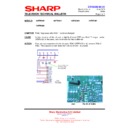
Horizontal Drive Problems
Sometimes it will appear that there is no horizontal drive signal, even though the microprocessor has gone through the
boot sequence. In this situation, it is possible to release the horizontal mute to enable the horizontal stage to start.
There are a number of ways that this can be achieved, one is to short out the base/emitter junction of Q607, and the
other is to temporarily isolate link JL2. If this link is removed, it is vital that it is replaced after completing the repair as
failure to do so will result in premature failure of the line stage.
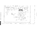
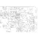
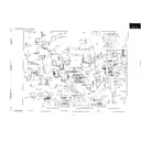
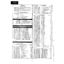
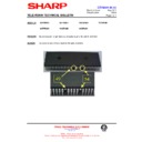
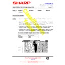
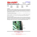
Location of Link Wire JL2
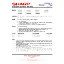
REF NO
DESCRIPTION
PART NUMBER
PRICE CODE
C528
Capacitor 10
µ
F 63V
VCEAGA1JW106M
AA
C607
Capacitor, 330
µ
F, 10V
VCEAGAIAW337M
AB
C613
Capacitor, 560nF 250V
RC-FZ6564BMNJ
AF
C615
Capacitor, 470
µ
F 25V
VCEAGA1EW477M
AB
C632
Capacitor, 470
µ
F 25V
VCEAGA1EW477M
AB
D1601
Zener Diode, BZX79C33V
RH-EX0427BMZZ
AA
IC705
IC, MOC8106SR2V-M
RH-IX0106BMZZ
AD
L603
Coil
RCILP0286BMZZ
AG
Q506
Transistor E/W
RH-TX0151BMZZ
AD
Q601
Transistor Line o/p
RH-TX0144BMZZ
AK
R610
Safety Resistor
RR-XZ0200BMZZ
AB
R613
Resistor, 3.3k
Ω
3W
VRS-LU3LB332J
AB
Display

