Sharp MX-3500N / MX-3501N / MX-4500N / MX-4501N (serv.man9) Service Manual ▷ View online
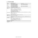
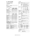
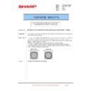
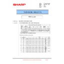
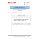
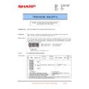
MX3500N SIMULATION 7 – 17
6-2
Purpose
Operation test/check
Function (Purpose) Used to check the operations of each fan
motor and its control circuit.
Section
Other
Item
Operation
Operation/Procedure
1) Select the item to be checked with the buttons on the touch
1) Select the item to be checked with the buttons on the touch
panel.
2) Press [EXECUTE] button.
The selected load operation is performed.
When [EXECUTE] button is pressed, the operation is termi-
nated.
When [EXECUTE] button is pressed, the operation is termi-
nated.
6-3
Purpose
Operation test/check
Function (Purpose) Used to check the operations of the primary
transfer unit and the related circuit.
Section
Process (Transfer)
Item
Operation
Operation/Procedure
1) Press [EXECUTE] button.
2) The load operation is started. (Separation operation: BLACK
1) Press [EXECUTE] button.
2) The load operation is started. (Separation operation: BLACK
→ COLOR → FREE Stops at each position for 5 sec.) During
the operation, the current position is displayed.
the operation, the current position is displayed.
7
7-1
Purpose
Setting
Function (Purpose) Used to set the operating conditions of
aging.
Section
Other
Item
Operation
Operation/Procedure
1)
1)
Select the target to be set with buttons on the touch panel.
2)
Press [EXECUTE] button.
The machine is rebooted in the aging mode.
The contents set with this simulation are retained until the
power is turned OFF.
The machine is rebooted in the aging mode.
The contents set with this simulation are retained until the
power is turned OFF.
7-6
Purpose
Setting
Function (Purpose) Used to set the intermittent aging cycle.
Section
Section
Other
Item
Operation
Operation/Procedure
1)
1)
Enter the intermittent aging cycle (unit: sec) with 10-key.
2)
Press [OK] button.
The time entered in procedure 1) is set.
The time entered in procedure 1) is set.
POFM
Paper exit cooling fan motor (* POFM_U, POFM_F, and
POFM_R are driven at the same time.)
POFM_R are driven at the same time.)
OZFM
Ozone fan motor
PSFM
Power cooling fan motor
LSUFM
LSU cooling fan motor
BLACK
Black mode position
Black mode position
→ COLOR mode position
→ Drum separation position
→ Shift to the black mode
position is repeated.
→ COLOR mode position
→ Drum separation position
→ Shift to the black mode
position is repeated.
COLOR
COLOR mode position
FREE
Drum separation position
㩷
㩷
㩷
㩷
㩷
㩷
㩷
㩷
㩷
㩷
㩷
㩷
㩷
㩷
㩷
㩷
CLOSE
0
SIMULATION
NO.06̆01
TEST
FEED
OUTPUT CHECK
EXECUTE
1/2
PFM
FUM
CPFM
OSM
CPFC
1TURC
PCSS
WTNM
CLUM1
CPUC1
CLUM2
CPUC2
MPUC
RRM
POMF
POMR
㩷
㩷
㩷
㩷
㩷
㩷
㩷
㩷
㩷
㩷
㩷
㩷
㩷
SIMULATION
NO.06̆02
TEST
FAN
LOAD
SETUP
POFM
OZFM
LSUFM
PSFM
1/1
EXECUTE
0
CLOSE
0
SIMULATION
NO.06̆03
TEST
TRANSFER LOAD CHECK
EXECUTE
POSITION
̆̆
:
1/1
CLOSE
AGING
Aging operation setup
INTERVAL
Intermittent setup
MISFEED DISABLE
JAM detection enable/disable setup
FUSING DISABLE
Fusing operation enable/disable setup
WARMUP DISABLE
Warm-up disable setup
DV CHECK DISABLE
DV unit detection enable/disable setup
SHADING DISABLE
Shading disable setup
CCD GAIN FREE
CCD gain adjustment free setup
Item
Item
Set range
Default value
A
CYCLE TIME(SEC)
1 to 900
3
SIMULATION
NO.07̆01
TEST
AGING
TEST SETTING
AGING
INTERVAL
MISFEED
DISABLE
FUSING
DISABLE
WARMUP
DISABLE
DV
CHECK
DISABLE
1/1
EXECUTE
0
SHADING
DISABLE
CCD
GAIN
FREE
CLOSE
0
A:
A
㧦 3
㧧 CYCLE TIME(SEC)
SIMULATION
NO.07-06
INTERVAL
AGING CYCLE TIME SETUP
3
㨇 1㨪 900 㨉
OK
TEST
CLOSE
MX3500N SIMULATION 7 – 18
7-8
Purpose
Operation display
Function (Purpose) Used to display the warm-up time.
Section
Section
Fusing
Item
Operation
Operation/Procedure
Press [EXECUTE] button.
Counting of the warm-up time is started.
* Interruption of counting by pressing [EXECUTE] button is inhib-
Press [EXECUTE] button.
Counting of the warm-up time is started.
* Interruption of counting by pressing [EXECUTE] button is inhib-
ited.
7-9
Purpose
Operation test/check
Function (Purpose) Used to check printing in the color mode.
Section
Section
—
Item
Operation
Operation/Procedure
1) Select a print color with buttons on the touch panel.
2) Press [EXECUTE] button.
1) Select a print color with buttons on the touch panel.
2) Press [EXECUTE] button.
Printing is started in the selected color.
* If no color is specified, printing is made in all colors.
8
8-1
Purpose
Operation test/Check/Adjustment
Function (Purpose) Used to check and adjust the operations of
the developing voltage of each color and
the control circuit.
the control circuit.
Section
Process (Photoconductor/Developing/
Transfer/Cleaning)
Transfer/Cleaning)
Item
Operation
Operation/Procedure
1) Select a speed with [MIDDLE] and [LOW] (MX-4500N/4501N:
1) Select a speed with [MIDDLE] and [LOW] (MX-4500N/4501N:
[LOW/HIGH]) buttons on the touch panel.
2)
Select a target item to be adjusted with [
↑] [↓] buttons.
3)
Enter the adjustment value with 10-key.
4)
Press [EXECUTE] button.
The set value is saved and the voltage corresponding to the
set value is outputted for 30 sec.
The set value is saved and the voltage corresponding to the
set value is outputted for 30 sec.
* The adjustment values of [MIDDLE] and [LOW] (MX-4500N/
4501N: [LOW/HIGH]) are related together.
* When [EXECUTE] button is pressed, the output is terminated.
8-2
Purpose
Operation test/Check/Adjustment
Function (Purpose) Used to check and adjust the operation of
the main charger grid voltage in each
printer mode and the control circuit.
printer mode and the control circuit.
Section
Process (Photoconductor/Developing/
Transfer/Cleaning)
Transfer/Cleaning)
Item
Operation
Operation/Procedure
1)
1)
Select a speed with [MIDDLE] and [LOW] (MX-4500N/4501N:
[LOW/HIGH]) buttons on the touch panel.
[LOW/HIGH]) buttons on the touch panel.
2)
Select a target item to be adjusted with [
↑] [↓] buttons.
3)
Enter the adjustment value with 10-key.
4)
Press [EXECUTE] button.
The set value is saved and the voltage corresponding to the
set value is outputted for 30 sec.
The set value is saved and the voltage corresponding to the
set value is outputted for 30 sec.
* The adjustment values of [MIDDLE] and [LOW] (MX-4500N/
4501N: [LOW/HIGH]) are related together.
* When [EXECUTE] button is pressed, the output is terminated.
K
Setup/cancel of black
C
Setup/cancel of cyan
M
Setup/cancel of magenta
Y
Setup/cancel of yellow
0
SIMULATION NO.07
̆08
TEST
WARM
UP
TIME
DISPLAY
SETTING
CLOSE
EXECUTE
0
SECONDS
CLOSE
0
K
SIMULATION
NO.07̆09
TEST
PRINTING
COLOR
SELECT(COLOR
MODE)
C
M
Y
1/1
EXECUTE
Button
Item
Display
Content
Setting
range
Default
value
MIDDLE
A
MIDDLE
SPEED
DVB_K
SPEED
DVB_K
K developing
bias set value at
middle speed
bias set value at
middle speed
0 to 700
450
B
MIDDLE
SPEED
DVB_C
SPEED
DVB_C
C developing
bias set value at
middle speed
bias set value at
middle speed
0 to 700
450
C
MIDDLE
SPEED
DVB_M
SPEED
DVB_M
M developing
bias set value at
middle speed
bias set value at
middle speed
0 to 700
450
D
MIDDLE
SPEED
DVB_Y
SPEED
DVB_Y
Y developing
bias set value at
middle speed
bias set value at
middle speed
0 to 700
450
LOW
A
LOW
SPEED
DVB_K
SPEED
DVB_K
K developing
bias set value at
low speed
bias set value at
low speed
0 to 700
430
B
LOW
SPEED
DVB_C
SPEED
DVB_C
C developing
bias set value at
low speed
bias set value at
low speed
0 to 700
430
C
LOW
SPEED
DVB_M
SPEED
DVB_M
M developing
bias set value at
low speed
bias set value at
low speed
0 to 700
430
D
LOW
SPEED
DVB_Y
SPEED
DVB_Y
Y developing
bias set value at
low speed
bias set value at
low speed
0 to 700
430
HIGH
(MX-4500N/
4501N only)
(MX-4500N/
4501N only)
E
HIGH
SPEED
DVB_K
SPEED
DVB_K
K developing
bias set value at
high speed
bias set value at
high speed
0 to 700
450
㩷
0
A:
A
㧦450
B
㧦450
C
㧦450
㧧 MIDDLE SPEED DVB_K
㧧 MIDDLE SPEED DVB_C
㧧 MIDDLE SPEED DVB_M
SIMULATION
NO.08㧙01
DV
SETTING
AND
OUTPUT
450
㨇 0㨪 700㨉
OK
TEST
CLOSE
EXECUTE
D
㧦450
㧧 MIDDLE SPEED DVB_Y
LOW
MIDDLE
MX3500N SIMULATION 7 – 19
8-6
Purpose
Operation test/Check/Adjustment
Function (Purpose) Used to check and adjust the operation of
the transfer voltage and the control circuit.
Section
Process (Photoconductor/Developing/
Transfer/Cleaning)/Transfer
Transfer/Cleaning)/Transfer
Item
Setting
Operation/Procedure
1)
1)
Select a target item to be adjusted with [
↑] [↓] buttons.
2)
Enter the adjustment value with 10-key.
3)
Press [EXECUTE] button.
The set value is saved and the voltage corresponding to the
set value is outputted for 30 sec.
When [EXECUTE] button is pressed, the output is terminated.
The set value is saved and the voltage corresponding to the
set value is outputted for 30 sec.
When [EXECUTE] button is pressed, the output is terminated.
(MX-3500N/3501N)
(MX-4500N/4501N)
Button
Item
Display
Content
Setting
range
Default
value
MIDDLE
A
MIDDLE
SPEED
GB_K
SPEED
GB_K
K charging/grid
bias set value at
middle speed
bias set value at
middle speed
230 to 850
645
B
MIDDLE
SPEED
GB_C
SPEED
GB_C
C charging/grid
bias set value at
middle speed
bias set value at
middle speed
230 to 850
645
C
MIDDLE
SPEED
GB_M
SPEED
GB_M
M charging/grid
bias set value at
middle speed
bias set value at
middle speed
230 to 850
645
D
MIDDLE
SPEED
GB_Y
SPEED
GB_Y
Y charging/grid
bias set value at
middle speed
bias set value at
middle speed
230 to 850
645
LOW
A
LOW
SPEED
GB_K
SPEED
GB_K
K charging/grid
bias set value at
low speed
bias set value at
low speed
230 to 850
620
B
LOW
SPEED
GB_C
SPEED
GB_C
C charging/grid
bias set value at
low speed
bias set value at
low speed
230 to 850
620
C
LOW
SPEED
GB_M
SPEED
GB_M
M charging/grid
bias set value at
low speed
bias set value at
low speed
230 to 850
620
D
LOW
SPEED
GB_Y
SPEED
GB_Y
Y charging/grid
bias set value at
low speed
bias set value at
low speed
230 to 850
620
HIGH
(MX-4500N/
4501N only)
(MX-4500N/
4501N only)
E
HIGH
SPEED
GB_K
SPEED
GB_K
K charging/grid
bias set value at
high speed
bias set value at
high speed
230 to 850
665
0
A:
A
㧦645
B
㧦645
C
㧦645
㧧 MIDDLE SPEED GB_K
㧧 MIDDLE SPEED GB_C
㧧 MIDDLE SPEED GB_M
SIMULATION
NO.08㧙02
MHV/GRID
SETTING AND OUTPUT
645
㨇230㨪 850㨉
OK
TEST
CLOSE
EXECUTE
D
㧦645
㧧 MIDDLE SPEED GB_Y
LOW
MIDDLE
Item
Display
Content
Setting
range
Default
value
Actual output
setting range
Default
value
Actual
output value
A
TC1 LOW SPEED CL K
Primary transfer
bias reference
value
bias reference
value
COLOR
K
Low speed
0 to 255
232
–500V to 5000V
4500V
B
TC1 MIDDLE SPEED CL K
Middle speed
0 to 255
232
–500V to 5000V
4500V
C
TC1 LOW SPEED CL CMY
CMY
Low speed
0 to 255
139
–500V to 5000V
2500V
D
TC1 MIDDLE SPEED CL CMY
Middle speed
0 to 255
139
–500V to 5000V
2500V
E
TC1 LOW SPEED BW K
BLACK
K
Low speed
0 to 255
232
–500V to 5000V
4500V
F
TC1 MIDDLE SPEED BW K
Middle speed
0 to 255
232
–500V to 5000V
4500V
G
TC2 PLAIN CL SPX
Secondary transfer
bias reference
value
bias reference
value
COLOR
Normal
paper
Front surface
51 to 255
136
2
µA to 45µA
20
µA
H
TC2 PLAIN CL DPX
Back surface
51 to 255
136
2
µA to 45µA
20
µA
I
TC2 PLAIN BW SPX
BLACK
Front surface
51 to 255
117
2
µA to 45µA
16
µA
J
TC2 PLAIN BW DPX
Back surface
51 to 255
117
2
µA to 45µA
16
µA
K
TC2 HEAVY CL SPX
COLOR
Heavy
paper
Front surface
51 to 255
79
2
µA to 45µA
8
µA
L
TC2 HEAVY CL DPX
Back surface
51 to 255
70
2
µA to 45µA
6
µA
M
TC2 HEAVY BW SPX
BLACK
Front surface
51 to 255
79
2
µA to 45µA
8
µA
N
TC2 HEAVY BW DPX
Back surface
51 to 255
70
2
µA to 45µA
6
µA
O
TC2 OHP CL
COLOR
OHP
51 to 255
65
5
µA to 45µA
5
µA
P
TC2 OHP BW
BLACK
51 to 255
65
5
µA to 45µA
5
µA
Q
TC2 ENVELOPE CL
COLOR
Envelope
51 to 255
184
5
µA to 45µA
30
µA
R
TC2 ENVELOPE BW
BLACK
51 to 255
184
5
µA to 45µA
30
µA
S
TC2 CLEANING
Cleaning process
51 to 255
79
5
µA to 45µA
8
µA
T
TC2 CLEAN LOW SPD
Secondary transfer
cleaning bias
reference value
cleaning bias
reference value
Low speed print
51 to 255
72
–50V to –1500V
–200V
U
TC2 CLEAN MIDDLE SPD
Middle speed print
51 to 255
100
–50V to –1500V
–400V
V
TC2 CLEAN CLEANING
Cleaning
51 to 255
156
–50V to –1500V
–800V
Item
Display
Content
Setting
range
Default
value
Actual output
setting range
Default
value
Actual
output value
A
TC1 LOW SPEED CL K
Primary transfer
bias reference
value
bias reference
value
COLOR
K
Low speed
0 to 255
232
–500V to 5000V
4500V
B
TC1 MIDDLE SPEED CL K
Middle speed
0 to 255
232
–500V to 5000V
4500V
C
TC1 LOW SPEED CL CMY
CMY
Low speed
0 to 255
139
–500V to 5000V
2500V
D
TC1 MIDDLE SPEED CL CMY
Middle speed
0 to 255
139
–500V to 5000V
2500V
E
TC1 LOW SPEED BW K
BLACK
K
Low speed
0 to 255
232
–500V to 5000V
4500V
F
TC1 MIDDLE SPEED BW K
Middle speed
0 to 255
232
–500V to 5000V
4500V
G
TC1 HIGH SPEED BW K
High speed
0 to 255
232
–500V to 5000V
4500V
MX3500N SIMULATION 7 – 20
9
9-2
Purpose
Operation test/check
Function (Purpose) Used to check the operations of the sen-
sors and detectors in the duplex section
and its control circuit.
and its control circuit.
Section
Duplex
Item
Operation
Operation/Procedure
The sensor and detector operation conditions are displayed.
The active sensors and detectors are highlighted.
The sensor and detector operation conditions are displayed.
The active sensors and detectors are highlighted.
9-3
Purpose
Operation test/check
Function (Purpose) Used to check the operations of the loads
in the duplex section and the control cir-
cuits.
cuits.
Section
Duplex
Item
Operation
Operation/Procedure
1)
1)
Select the item to be operation tested with the buttons on the
touch panel.
touch panel.
2)
Press [EXECUTE] button.
The selected load operation is performed.
When [EXECUTE] button is pressed, the output is terminated.
The selected load operation is performed.
When [EXECUTE] button is pressed, the output is terminated.
10
10-1
Purpose
Operation test/check
Function (Purpose) Used to check the operations of the toner
motor and the related circuit.
Section
Process (Developing)
Item
Operation
Operation/Procedure
* Before execution of this simulation, remove the toner cartridges.
1)
* Before execution of this simulation, remove the toner cartridges.
1)
Select the item to be checked with the buttons on the touch
panel.
panel.
2)
Press [EXECUTE] button.
* The selected load operation is performed for 10 sec.
* When [EXECUTE] button is pressed, the operation is termi-
* The selected load operation is performed for 10 sec.
* When [EXECUTE] button is pressed, the operation is termi-
nated.
H
TC2 PLAIN CL SPX
Secondary transfer
bias reference
value
bias reference
value
COLOR
Normal
paper
Front surface
51 to 255
136
2
µA to 45µA
20
µA
I
TC2 PLAIN CL DPX
Back surface
51 to 255
136
2
µA to 45µA
20
µA
J
TC2 PLAIN BW SPX
BLACK
Front surface
51 to 255
117
2
µA to 45µA
16
µA
K
TC2 PLAIN BW DPX
Back surface
51 to 255
117
2
µA to 45µA
16
µA
L
TC2 HEAVY CL SPX
COLOR
Heavy
paper
Front surface
51 to 255
79
2
µA to 45µA
8
µA
M
TC2 HEAVY CL DPX
Back surface
51 to 255
70
2
µA to 45µA
6
µA
N
TC2 HEAVY BW SPX
BLACK
Front surface
51 to 255
79
2
µA to 45µA
8
µA
O
TC2 HEAVY BW DPX
Back surface
51 to 255
70
2
µA to 45µA
6
µA
P
TC2 OHP CL
COLOR
OHP
51 to 255
65
5
µA to 45µA
5
µA
Q
TC2 OHP BW
BLACK
51 to 255
65
5
µA to 45µA
5
µA
R
TC2 ENVELOPE CL
COLOR
Envelope
51 to 255
184
5
µA to 45µA
30
µA
S
TC2 ENVELOPE BW
BLACK
51 to 255
184
5
µA to 45µA
30
µA
T
TC2 CLEANING
Cleaning process
51 to 255
79
5
µA to 45µA
8
µA
U
TC2 CLEAN LOW SPD
Secondary transfer
cleaning bias
reference value
cleaning bias
reference value
Low speed print
51 to 255
72
–50V to –1500V
–200V
V
TC2 CLEAN MIDDLE SPD
Middle speed print
51 to 255
100
–50V to –1500V
–400V
W
TC2 CLEAN HIGH SPD
High speed print
51 to 255
114
–50V to –1500V
–500V
X
TC2 CLEAN CLEANING
Cleaning
51 to 255
156
–50V to –1500V
–800V
Item
Display
Content
Setting
range
Default
value
Actual output
setting range
Default
value
Actual
output value
DSW_ADU
ADU transport open/close detection
APPD1
ADU transport path detection 1
APPD2
ADU transport path detection 2
CLOSE
A:
A : 232
B : 232
C : 139
TC1 LOW SPEED CL K
TC1 MIDDLE SPEED CL K
TC1 LOW SPEED CL CMY
SIMULATION
NO.08-06
THV SETTING AND OUTPUT
232
[
0~255]
OK
TEST
EXECUTE
0
D : 139
TC1
MIDDLE SPEED CL
CMY
CLOSE
0
ADU
SENSOR CHECK
1/1
CLOSE
SIMULATION
NO.09㧙02
TEST
1/1
DSW_ADU
APPD1
APPD2
ADUM_L
ADU motor lower
ADUM_U
ADU motor upper
ADUGS
ADU gate solenoid
0
SIMULATION
NO.09-03
TEST
ADU LOAD CHECK
EXECUTE
1/1
ADUM_L
ADUM_U
ADUGS
CLOSE

