Sharp XG-P25XE (serv.man7) Service Manual ▷ View online
XG-P25X
16
Reassembling precautions
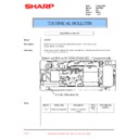
5-7. Fit part a of the input PWB to the slit of the bottom cover.
5-8. Align the input PWB’s shield with the top of the AC inlet shield ( b ).
5-9. Before tightening up the screws (5-7) as well as the screws and hex nuts (5-8), move the PWB unit forward
5-8. Align the input PWB’s shield with the top of the AC inlet shield ( b ).
5-9. Before tightening up the screws (5-7) as well as the screws and hex nuts (5-8), move the PWB unit forward
enough ( c ).
PWB Unit Ass'y
XG-P25X
17
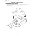
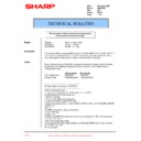
6. Removing the power / ballast / sound-out / bimetal unit assembly.
6-1. Remove the screw and disconnect the grounding wire from the shield case of the power/ballast unit.
6-2. Disconnect the connectors from the sound out PWB.
6-3. Take out the bimetal socket.
6-4. Remove the two screws and detach the lamp socket.
6-5. Remove the three screws and detach the power unit.
6-6. Remove the screw and slide the bimetal assembly upward out of position.
6-2. Disconnect the connectors from the sound out PWB.
6-3. Take out the bimetal socket.
6-4. Remove the two screws and detach the lamp socket.
6-5. Remove the three screws and detach the power unit.
6-6. Remove the screw and slide the bimetal assembly upward out of position.
6-5
6-1
6-2
6-3
6-3
6-6
6-4
Bimetal Ass'y
Sound Out PWB
Power/Ballast Unit
XG-P25X
18
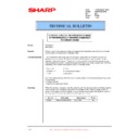
7. Removing the optical mechanism unit
7-1. Remove the two screws off the optical mechanism intake fan.
7-2. Remove the eight screws and take out the optical mechanism unit.
7-3. Remove the screw and disconnect the grounding wire.
7-4. Disconnect the connector and detach the AC inlet unit.
7-2. Remove the eight screws and take out the optical mechanism unit.
7-3. Remove the screw and disconnect the grounding wire.
7-4. Disconnect the connector and detach the AC inlet unit.
7-2
7-2
7-1
7-3
7-4
7-2
7-2
Optical Mechanism Unit
AC Inlet Unit
Display

