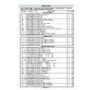
Sharp R-875M (serv.man2) Service Manual / Parts Guide ▷ View online
R-875/885 -
45
Note: The parts marked "
∆
" may cause undue microwave exposure. / The parts marked "*" are used in
voltage more than 250V. / "§" Mark: Spare parts delivery section
REF. NO.
PART NO.
§
DESCRIPTION
Q'TY CODE
PARTS LIST
*
∆
*
*
*
ELECTRIC PARTS
C
RC-QZA240WRE0
U
High voltage capacitor
1
AR
CM
RMOTEA373WRE0
U
Convection motor
1
AV
F1
QFS-BA009WRE0
U
Fuse 20A
1
AC
F2
QFS-CA025WRE0
U
Fuse F8A
1
AC
FM
RMOTEA361WRE0
U
Fan motor
1
AT
GH1
RHET-A254WRZZ
U
Top grill heating element
1
AT
GH2
RHET-A248WRZ1
U
Bottom grill heating element
1
AW
MG
RV-MZA243WRE1
U
Magnetron
1
BH
OL
RLMPTA066WRE0
U
Oven lamp
1
AK
SW1
QSW-MA146WRZZ
J
Monitored latch switch
1
AC
SW2
QSW-MA147WRZZ
J
Stop switch
1
AG
SW3
QSW-MA146WRZZ
J
Monitor switch
1
AC
T
RTRN-A019URE0
U
High voltage transformer
1
BF
TC1
RTHM-A098WRE0
U
Thermal cut-out 125˚C off(MG)
1
AH
TC2
RTHM-A124WRZZ
U
Thermal cut-out 145˚C off 115˚C on (OVEN)
1
AH
TTM
RMOTDA227WRE0
U
Turntable motor
1
AU
1- 1
FH-HZA075WRE0
U
Thermistor
1
AN
1- 2
RTRN-A529WRE0
U
TC transformer
1
AV
1- 3
QACCVA004URE2
U
Power supply cord
1
AQ
1- 4
FH-DZA035WRE0
U
High voltage rectifier assembly
1
AP
1- 5
FPWBFA309WRE2
U
Noise filter
1
AT
CABINET PARTS
2- 1
GCABDA001URP2
U
Back plate
1
AQ
2- 2
GCABDA002URP0
U
Sub back plate
1
AH
2- 3
GCABUW441URP0
U
Outer case cabinet [R-875(B)]
1
AX
2- 3
GCABUW468URT0
U
Outer case cabinet [R-875(W)]
1
AX
2- 3
GCABUW419URP0
U
Outer case cabinet [R-875(K)]
1
AX
2- 3
GCABUW045URP0
U
Outer case cabinet [R-885(AL)]
1
AW
2- 4
GDAI-A002URP0
U
Base plate
1
AR
2- 5
GLEGPA057WRE1
U
Foot
2
AB
CONTROL PANEL PARTS
3- 1
DPWBFA184URK0
U
Power unit
1
BC
3- 1A
QCNCMA453DRE0
U
5-pin connector (CN-A)
1
AC
3- 1B
QCNCMA414DRE0
U
2-pin connector (CN-B)
1
AB
3- 1C
QCNCMA410DRE0
U
2-pin connector (CN-C)
1
AB
3- 1D
QCNCMA230DRE0
U
4-pin connector (CN-E)
1
AC
3- 1E
FW-VZA266DREZ
U
15pin wire harness (WH-1)
1
AH
C1
RC-KZA087DRE0
U
Capacitor 0.1 uF 50V
1
AB
C2
VCEAG31VW108M
U
Capacitor 1000 uF 35V
1
AE
C3
RC-KZA087DRE0
U
Capacitor 0.1 uF 50V
1
AB
C4-5
VCEAG31VW106M
U
Capacitor 10 uF 35V
2
AB
D1-7
VHD1SS270A/-1
U
Diode (1SS270A)
7
AA
D11-14
VHD1N4005E/-2
U
Diode (1N4005E)
4
AA
D11-14
VHD1N4004S/-1T U
Diode (1N4004S) (Interchangeable)
4
AA
Q2
VSKTA1274//-3
U
Transistor (KTA1274)
1
AA
Q3
VSKRC243M//-3
U
Transistor (KRC243M)
1
AB
R2
VRD-B12EF152J
U
Resistor 1.5K ohm 1/4W
1
AA
R3-4
VRS-B13AA511J
U
Resistor 510 ohm 1W
2
AB
R5
VRD-B12EF332J
U
Resistor 3.3K ohm 1/4W
1
AA
R6
VRS-B13AA201J
U
Resistor 200 ohm 1W
1
AB
RY1
RRLY-A117DRE0
U
Relay (DU18D1-1P(M)-R)
1
AG
RY2
RRLY-A122DRE0
U
Relay (DU18D1-1P(M)-R-S)
1
AG
RY3-4
RRLY-A113DRE0
U
Relay (DU24D1-1P(M)-R)
2
AG
RY5-7
RRLY-B004MRE0
U
Relay (FTR-F3AA024E)
3
AL
SP1
RALM-A014DRE0
U
Buzzer (PKM22EPT)
1
AG
VRS1
RH-VZA034DRE0
U
Varistor (10G471K)
1
AD
ZD2
VHEHZ201///-1
U
Zener diode (HZ20-1)
1
AB
3- 2
DPWBFC237WRKZ
U
CPU unit
1
BC
3- 3
FPWBFA060URK0
U
Jog switch unit
1
AS
3- 3-1
FW-VZA277DREZ
U
13-pin harness (CN-J)
1
AE
3- 3-2
RVR-BA014DRE0
U
Potentiometer (VR1)
1
AD
3- 3-3
RVR-BA018WRE0
U
Rotary encoder (RSW1)
1
AH
3- 3-4
QSW-K0005AWZZT U
Tact switch (SW1-SW13)
13
AD
3- 4
LHLD-A007URF1
U
LCD holder
1
AD
3- 5
PSHEPA647WRE0
U
LCD sheet
1
AL
3- 6
GMADIA038URR0
U
Display window [R-875(W)]
1
AH
3- 6
GMADIA038URR0
U
Display window [R-885(AL)]
1
AH
3- 6
GMADIA039URR0
U
Display window [R-875(B/K)]
1
AH
3- 7
HPNLCA121URR0
U
Control panel [R-885(AL)]
1
AQ
R-875/885 -
46
∆
∆
∆
∆
∆
∆
∆
∆
∆
∆
Note: The parts marked "
∆
" may cause undue microwave exposure. / The parts marked "*" are used in
voltage more than 250V. / "§" Mark: Spare parts delivery section
REF. NO.
PART NO.
§
DESCRIPTION
Q'TY CODE
∆
∆
3- 7
HPNLCB036URR0
U
Control panel [R-875(B)]
1
AQ
3- 7
HPNLCK016URR0
U
Control panel [R-875(K)]
1
AQ
3- 7
HPNLCW075URR0
U
Control panel [R-875(W)]
1
AQ
3- 8
JBTN-O016URF0
U
Express pizza button
1
AE
3- 9
JBTN-A102URT0
U
Auto cook button [R-885(AL)]
1
AP
3- 9
JBTN-B020URF0
U
Auto cook button [R-875(B)]
1
AD
3- 9
JBTN-K034URF0
U
Auto cook button [R-875(K)]
1
AD
3- 9
JBTN-W031URF0
U
Auto cook button [R-875(W)]
1
AD
3- 10
JBTN-A103URT0
U
Stop/Watt button [R-885(AL)]
1
AP
3- 10
JBTN-B021URF0
U
Stop/Watt button [R-875(B)]
1
AD
3- 10
JBTN-K033URF0
U
Stop/Watt button [R-875(K)]
1
AD
3- 10
JBTN-W032URF0
U
Stop/Watt button [R-875(W)]
1
AD
3- 11
JBTN-A104URT0
U
More/Less button [R-875(W)[R-885(AL)]
1
AW
3- 11
JBTN-K035URF0
U
More/Less button [R-875(B/K)]
1
AD
3- 12
JKNBKA042URT0
U
Vari knob [R-885(AL)]
1
AE
3- 12
JKNBKB012URF0
U
Vari knob [R-875(B)]
1
AE
3- 12
JKNBKK012URF0
U
Vari knob [R-875(K)]
1
AE
3- 12
JKNBKW013URF0
U
Vari knob [R-875(W)]
1
AE
3- 13
JKNBKA043URT0
U
Timer knob [R-885(AL)]
1
AE
3- 13
JKNBKB013URF0
U
Timer knob [R-875(B)]
1
AE
3- 13
JKNBKK013URF0
U
Timer knob [R-875(K)]
1
AE
3- 13
JKNBKW014URF0
U
Timer knob [R-875(W)]
1
AE
3- 14
MSPR-A002URE0
U
Spring
1
AB
3- 15
XEPSD30P10XS0
U
Screw : 3mm x 10mm
12
AA
OVEN PARTS
4- 1
DOVN-A023URK0
U
Oven cavity
1
BG
4- 2
LBNDKA107WRP1
U
Capacitor holder
1
AD
4- 3
FDUC-A003URY0
U
Air duct assembly
1
AL
4- 4
LANGQA005URP0
U
Air separate angle B
1
AC
4- 5
PDUC-A636WRP1
U
Air guide duct
1
AM
4- 6
PFILWA001URP0
U
Lamp filter
1
AB
4- 7
PHOK-A002URF1
U
Latch hook
1
AH
4- 8
LANGQA014URP0
U
Turntable motor angle
1
AE
4- 9
PCUSUA019URE0
U
Cushion
1
AA
4-10
FANGTA003URY0
U
Turntable motor shaft assembly
1
AL
4-11
PPACGA002URE0
U
Seal packing
1
AB
4-12
NFANJA038WRE0
U
Fan blade
1
AF
4-13
PDUC-A637WRF2
U
Fan duct
1
AL
4-14
NFANMA002URP0
U
Cooling fan
1
AF
4-15
GCOVHA001URP1
U
Bottom heater cover
1
AM
4-16
LANGFA155WRP7
U
Chassis support
1
AF
4-17
PPACGA001URE0
U
Heater packing
1
AD
4-18
LANGQA008URP0
U
Grill heater angle
2
AD
4-19
NFANMA001URP0
U
Convection fan
1
AD
4-20
PSPAGA001WRE0
U
Vibration proof cushion
1
AA
4-21
PCUSUA006URE0
U
Air cushion B
1
AA
4-22
PCOVQA002URP0
U
Heater cover
1
AD
4-23
PCOVPA308WRE1
U
Waveguide cover
1
AE
4-24
PCUSUA015URE0
U
Back plate cushion
1
AB
4-25
PPIP-A001UR10
U
Pipe
1
AE
4-26
PCOVQA001URP0
U
Rear heat cover
1
AP
4-27
PDUC-A606WRF1
U
Air intake duct
1
AK
4-28
PDUC-A008URP0
U
Exhaust duct
1
AK
4-29
PSKR-A308WRF0
U
Rear barrier
1
AH
4-30
PDUC-A003URP0
U
Convection duct
1
AL
4-31
PCUSUA012URE0
U
Cushion
1
AB
4-32
LANGQA004URP0
U
Convection air angle
2
AN
DOOR PARTS
5- 1
DDORFA766WRK0
U
Door panel assembly
1
BE
5- 2
GWAKPB016URR0
U
Door frame [R-875(B)]
1
AU
5- 2
GWAKPK011URR0
U
Door frame [R-875(K)]
1
AU
5- 2
GWAKPW041URR0
U
Door frame [R-875(W)]
1
AU
5- 2
GWAKPA103URR0
U
Door frame [R-885(AL)]
1
AU
5- 3
LSTPPA017URF0
U
Latch head
1
AG
5- 4
LHLD-A012URF0
U
Glass holder [R-875(W)] [R-885(AL)]
1
AB
5- 4
LHLD-A013URF0
U
Glass holder [R-875(B)] [R-875(K)]
1
AC
5- 5
MSPRTA197WREZ
U
Latch spring
1
AC
5- 6
PGLSPA027URE0
U
Front door glass
1
AN
5- 7
JHNDPB001URF0
U
Door handle A [R-875(B)]
1
AE
5- 7
JHNDPK005URF0
U
Door handle A [R-875(K)]
1
AE
5- 7
JHNDPW002URF0
U
Door handle A [R-875(W)]
1
AK
PARTS LIST
R-875/885 -
47
Note: The parts marked "
∆
" may cause undue microwave exposure. / The parts marked "*" are used in
voltage more than 250V. / "§" Mark: Spare parts delivery section
REF. NO.
PART NO.
§
DESCRIPTION
Q'TY CODE
*
*
*
HOW TO ORDER REPLACEMENT PARTS
To have your order filled promptly and correctly, please furnish the following information.
1. MODEL NUMBER
3. PART NO.
2. REF. NO.
4. DESCRIPTION
PARTS LIST
5- 7
JHNDPA012URT0
U
Door handle A [R-885(AL)]
1
AK
5- 8
JHNDPB002URF0
U
Door handle B [R-875(B)]
1
AE
5- 8
JHNDPK006URF0
U
Door handle B [R-875(K)]
1
AE
5- 8
JHNDPW003URF0
U
Door handle B [R-875(W)]
1
AR
5- 8
JHNDPA013URT0
U
Door handle B [R-885(AL)]
1
AR
5- 9
XETSD40P30000
U
Screw: 4mm x 30mm
2
AA
5-10
XEBSD30P08000
U
Screw: 3mm x 8mm
3
AA
5-11
XEBSD30P06000
U
Screw: 3mm x 6mm
4
AA
5-12
GCOVHA365WRF3
U
Choke cover
1
AM
MISCELLANEOUS
6- 1
FAMI-A072WRK2
U
High rack
1
AT
6- 2
FAMI-A095WRK1
U
Low rack
1
AR
6- 3
LHLDKA008WRF1
U
P-clip
1
AA
6- 4
CTNT-A005URK0
U
Turntable tray
1
AY
6- 5
FW-VZA061URE1
U
Stop switch harness
1
AE
6- 7
QW-QZA210WRE1
U
High voltage wire B
1
AD
6- 8
FW-VZA098URE1
U
Main harness
1
AX
6- 9
TINS-A292URR0
U
Quick start guide
1
AD
6-10
TINS-A291URR0
U
Operation manual
1
AW
6-11
TLABMA205URR0
U
Menu label [R-875(W)][R-885(AL)]
1
AD
6-11
TLABMA207URR0
U
Menu label [[R-875(B)]R-875(K)]
1
AD
SCREWS,NUTS AND WASHERS
7- 1
XHPSD40P08K00
U
Screw: 4mm x 8mm
1
AA
7- 2
LX-NZ0061WRE0
J
M4 Flange nut
4
AA
7- 3
XWWSD50-06000
J
Washer: 5mm x 0.6mm
1
AA
7- 4
XOTSE40P10000
U
Screw: 4mm x 10mm [R-875(W)][R-885(AL)]
4
AA
7- 4
XOTSF40P10000
U
Screw: 4mm x 10mm [R-875(B)][R-875(K)]
4
AA
7- 5
XHPSD40P06000
J
Screw: 4mm x 6mm
3
AA
7- 6
XHTSD40P08RV0
J
Screw: 4mm x 8mm
6
AA
7- 7
XOTWW40P06000
J
Screw: 4mm x 6mm
10
AA
7- 8
XBTSD40P05000
U
Screw: 4mm x 5mm
2
AA
7- 9
XNEUW40-32000
J
Nut: 4mm x 3.2mm
1
AA
7-10
XOTSD40P12RV0
J
Screw: 4mm x 12mm
2
AA
7-11
XRESE40-06000
U
Ring
1
AA
7-12
XWHUW40-08000
U
Washer: 4mm x 0.8mm
1
AA
7-13
XWSUW40-10000
U
Washer: 4mm x 1.0mm
1
AA
7-14
XEPSD40P25000
J
Screw: 4mm x 25mm
2
AA
7-15
XBPWW30P05K00
U
Screw: 3mm x 5mm
2
AA
7-16
XWHUW50-08000
J
Washer: 5mm x 0.8mm
1
AA
7-17
XEBSD30P06000
J
Screw: 3mm x 6mm
3
AA
7-18
LX-CZA001URE0
U
Special screw
24
AA
7-19
XFPSD50P10KS0
U
Screw: 5mm x 10mm
2
AB
7-20
LX-EZA045WRE0
J
TTM cover screw
1
AA
R-875/885 -
48
OVEN PARTS
7-6
7-18
7-18
7-11
7-16
7-8
7-7
x7
x2
OL
4-25
4-14
4-26
4-30
1-3
4-32
4-27
4-32
4-19
7-12
7-13
7-9
4-3
CM
4-21
4-24
7-18
7-18
7-18
6-3
7-18
4-28
7-20
7-4
6-11
2-3
7-4
7-15
7-15
4-18
7-18
7-17
7-7
4-1
4-5
TC2
7-18
4-18
4-6
4-4
7-18
1-1
7-7
7-6
1-3
7-6
6-5
7-18
7-6
1-2
MG
SW3
SW2
7-17
7-18
7-10
4-7
7-6
7-17
7-14
7-1
TC1
4-16
F1
FM
4-13
4-12
1-4
7-6
7-19
4-29
4-20
4-31
7-18
7-18
2-4
2-5
2-5
7-3
T
4-2
4-15
7-5
7-2
7-2
TTM
7-5
4-10
4-22
4-17
4-11
4-8
6-4
4-23
GH2
4-9
C
F2
1-5
GH1
6-6
2-2
2-1
SW1
7-5
NOTE: In the event of removing the turn-
table motor cover this part should
be refitted using screw connec-
tion: LX-EZA045WRE0 (7-20)
be refitted using screw connec-
tion: LX-EZA045WRE0 (7-20)
OVEN PARTS DIAGRAM
Display


