Sharp XG-P25XE (serv.man5) Service Manual ▷ View online
XG-P25X
8
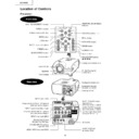
Location of Controls
Front View
Projector
MUTE button
VOLUME buttons (
/
)
MENU button
ADJUSTMENT buttons
(
(
/
/
/
)
AUTO SYNC button
RESIZE button
GAMMA button
Foot releases
POWER buttons (ON/OFF)
LENS button
ENTER button
INPUT 1, 2, 3, 4, 5 buttons
FREEZE button
BLACK SCREEN button
UNDO button
LAMP REPLACEMENT indicator
POWER indicator
Rear View
Air filter/Cooling fan
(Intake vent)
(Intake vent)
Cooling fan (Exhaust vent)
RS-232C INPUT port/
RS-232C OUTPUT port
INPUT 1 port (15-pin Mini D-sub)
VIDEO INPUT 4 terminal (RCA)
INPUT 3 port (DVI)
INPUT 2 terminals (BNC)
Computer AUDIO INPUT 2/3 terminal
(ø3.5 mm stereo minijack)
Computer AUDIO INPUT 1 terminal
(ø3.5 mm stereo minijack)
AUDIO OUTPUT terminal
(ø3.5 mm stereo minijack)
(ø3.5 mm stereo minijack)
WIRED REMOTE control
input terminal
(ø3.5 mm stereo minijack)
input terminal
(ø3.5 mm stereo minijack)
OUTPUT port (15-pin Mini
D-sub) for INPUT 1, 2
D-sub) for INPUT 1, 2
AUDIO INPUT 4/5
terminals (RCA)
terminals (RCA)
TEMPERATURE WARNING
indicator
indicator
S-VIDEO INPUT 5 terminal
(4-pin Mini DIN)
AC socket
Speakers
Kensington Security
Standard connector
Standard connector
Cooling fan (Intake vent)
Carrying handle
Lens shift dial
|
|
|
|
- +
XG-P25X
9
Operating the Wireless Mouse Remote Control
Remote Control
Front View
Top View
LENS button
ENTER button
ENLARGE buttons
AUTO SYNC button
GAMMA button
INPUT 1 button
INPUT 2 button
INPUT 4 button
UNDO button
POWER buttons (ON/OFF)
MENU button
FREEZE button
BLACK SCREEN button
INPUT 3 button
RESIZE button
INPUT 5 button
MUTE button
BREAK TIMER button
Adjustment (
/
/
/
)
buttons
VOLUME (
/
)
buttons
Wired RC jack (ø3.5 mm minijack)
|
|
|
|
-
+
XG-P25X
10
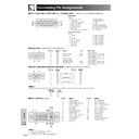
Connection Pin Assignments
RGB Input
Analog
1. Video input (red)
2. Video input
2. Video input
(green/sync on green)
3. Video input (blue)
4. Reserve input 1
5. Composite sync
6. Earth (red)
7. Earth (green/sync on green)
4. Reserve input 1
5. Composite sync
6. Earth (red)
7. Earth (green/sync on green)
8. Earth (blue)
9. Not connected
9. Not connected
10. GND
11. GND
12. Bi-directional data
13. Horizontal sync signal
14. Vertical sync signal
15. Data clock
11. GND
12. Bi-directional data
13. Horizontal sync signal
14. Vertical sync signal
15. Data clock
RS-232C Port:
9-pin D-sub male connector
5
10
15
15
1
6
11
6
11
INPUT 1 RGB and OUTPUT (INPUT 1, 2) Signal Ports:
15-pin Mini D-sub female connector
RS-232C Cable recommended connection:
9-pin D-sub female connector
Pin No.
Signal
Name
I/O
Reference
1
CD
Not connected
2
RD
Receive Data
Input
Connected to internal circuit
3
SD
Send Data
Output
Connected to internal circuit
4
ER
Not connected
5
SG
Signal Ground
Connected to internal circuit
6
DR
Data Set Ready
Not connected
7
RS
Request to Send
Output
Connected to internal circuit
8
CS
Clear to Send
Input
Connected to internal circuit
9
CI
Not connected
1
5
6
9
Signal
Signal
Pin No.
Pin No.
Component Input
Analog
1. P
R
(C
R
)
2. Y
3. P
3. P
B
(C
B
)
4. Not connected
5. Not connected
6. Earth (P
5. Not connected
6. Earth (P
R
)
7. Earth (Y)
8. Earth (P
8. Earth (P
B
)
9. Not connected
10. Not connected
11. Not connected
12. Not connected
13. Not connected
14. Not connected
15. Not connected
11. Not connected
12. Not connected
13. Not connected
14. Not connected
15. Not connected
INPUT 3 DVI Port:
29-pin
9
1
8 16
C1C2
C3
24
17
C4
C5
• *
1
Return for
5 V, Hsync. and Vsync.
• *
2
Analog R, G and B return
• *
3
These pins are not used on this equipment.
Pin No.
Name
1
T.M.D.S. Data 2
2
T.M.D.S. Data 2
3
T.M.D.S. Data 2/4 Shield
4
T.M.D.S. Data 4
*
3
5
T.M.D.S. Data 4
*
3
6
DDC Clock
7
DDC Data
8
Analog Vertical Sync
9
T.M.D.S. Data 1
10
T.M.D.S. Data 1
11
T.M.D.S. Data 1/3 Shield
12
T.M.D.S. Data 3
*
3
13
T.M.D.S. Data 3
*
3
14
5 V Power
15
Ground*
1
Pin No.
Name
16
Hot Plug Detect
17
T.M.D.S. Data 0
18
T.M.D.S. Data 0
19
T.M.D.S. Data 0/5 Shield
20
T.M.D.S. Data 5
*
3
21
T.M.D.S. Data 5
*
3
22
T.M.D.S. Clock Shield
23
T.M.D.S. Clock
24
T.M.D.S. Clock
C1
Analog Red
C2
Analog Green
C3
Analog Blue
C4
Analog Horizontal sync
C5
Analog Ground*
2
Projector
Pin No.
PC
Pin No.
5
9
1
CD
RD
SD
ER
SG
DR
RS
CS
CI
RD
SD
ER
SG
DR
RS
CS
CI
1
2
3
4
5
6
7
8
9
2
3
4
5
6
7
8
9
CD
RD
SD
ER
SG
DR
RS
CS
CI
RD
SD
ER
SG
DR
RS
CS
CI
1
2
3
4
5
6
7
8
9
2
3
4
5
6
7
8
9
6
4
5
6
5
6
4
5
6
5
6
Display

