Sharp XG-C55X (serv.man6) Service Manual ▷ View online
8
XG-C55X
OPERATION MANUAL
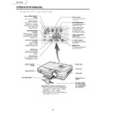
Projector (Front and Top View)
Power (ON/STANDBY)
buttons
Turn the power on or off.
Power indicator
Illuminates red, when the
projector is in standby.
When the power is turned
on, this indicator will
illuminate green.
Lamp replacement
indicator
Illuminates green indicating
normal function. Replace
the lamp when the indicator
illuminates red.
Temperature warning
indicator
When the internal
temperature rises, this
indicator will illuminate red.
UNDO button
For undoing an operation
or returning to the default
or returning to the default
settings.
ENTER button
For setting items selected
or adjusted on the menu.
Remote control
sensor
sensor
INPUT button
For switching input mode
1, 2, 3 or 4.
1, 2, 3 or 4.
KEYSTONE button
For adjusting Keystone or
Digital Shift setting.
Digital Shift setting.
AUTO SYNC button
For automatically
adjusting images when
connected to a computer.
adjusting images when
connected to a computer.
Adjustment buttons
(
(
,
,\
\
\
\, )
For selecting menu items.
VOLUME buttons
For adjusting the speaker
sound level.
sound level.
MENU button
For displaying adjustment
and setting screens.
and setting screens.
Zoom knob
Focus ring
Intake vent
HEIGHT ADJUST
button
Adjustment foot
Carrying handle
Air filter/cooling
fan (Intake vent)
(on the bottom of
the projector)
fan (Intake vent)
(on the bottom of
the projector)
Attaching and removing the lens cap
Press on the two buttons of the lens cap
and attach it on the lens. Then release
the b
and attach it on the lens. Then release
the b
•
•
uttons to lock it in place.
Press on the two buttons of the lens cap
and remove it from the lens.
and remove it from the lens.
9
XG-C55X
Projector (Rear View)
Using the Kensington Lock
This
•
projector has a Kensington Security Standard connector for use with a Kensington MicroSaver Security
System. Refer to the information that came with the system for instructions on how to use it to secure the
projector.
projector.
AC socket
Exhaust vent
Kensington Security
Standard connector
Standard connector
Adjustment Feet
INPUT 2 terminal
Terminal for
computer RGB and
component signals.
INPUT 1 terminal
Terminal for
computer RGB and
component signals.
OUTPUT (INPUT 1, 2)
terminal
Shared computer
RGB and component
signals output
terminal
for INPUT 1 and 2.
AUDIO OUTPUT
terminal
Shared audio
output terminal for
INPUT 1, 2, 3 and 4.
RS-232C terminal
For controlling
projector using a
computer.
AUDIO INPUT 1, 2
terminal
terminal
Shared audio input
terminal for INPUT 1
and 2.
terminal for INPUT 1
and 2.
INPUT 4 terminal
Terminal for
connecting video
equipment with an
S-video terminal
connecting video
equipment with an
S-video terminal
.
AUDIO (L/R)
INPUT 3, 4
terminals
INPUT 3, 4
terminals
Shared audio input
terminals for INPUT 3
and 4.
terminals for INPUT 3
and 4.
INPUT 3 terminal
For connecting
video equipment.
video equipment.
WIRED REMOTE
control input
terminal
control input
terminal
Carrying the projector
Before carrying the projector, fully
extend the carrying handle.
Before carrying the projector, fully
extend the carrying handle.
10
XG-C55X
Remote Control (Front View)
KEYSTONE button
For adjusting Keystone or Digital
Shift setting.
WIRED R/C JACK
For controlling the projector by
connecting the remote control to the
projector.
connecting the remote control to the
projector.
Power (ON/STANBY) buttons
For turning the power on or STANDBY.
MENU button
For displaying adjustment and
setting screens.
setting screens.
Adjustment buttons
(', ", \, |)
(', ", \, |)
For selecting menu items.
ENTER button
For setting items selected or
adjusted on the menu.
UNDO button
For undoing an operation or
returning to the default settings.
ENLARGE (Enlarge/Reduce)
buttons
For enlarging or reducing part of
the image.
AUTO SYNC button
For automatically adjusting images
when connected to a computer.
INPUT buttons
For switching to the respective
input modes.
GAMMA button
For correcting the brightness of an
image, when the images displayed
are hard to see because of the
brightness of the room. Four
gamma modes are available to
choose from.
VOLUME buttons
For adjusting the speaker sound
level.
Remote control signal transmitters
PinP button
For displaying dual pictures.
FORWARD/BACK buttons
Moves forward or backwards when
connected to a computer using a
USB cable. Same as the [Page
Down] and [Page Up] keys on a
computer keyboard.
connected to a computer using a
USB cable. Same as the [Page
Down] and [Page Up] keys on a
computer keyboard.
FREEZE button
For freezing images.
BLACK SCREEN button
For superimposing a black screen.
RESIZE button
For switching the screen size
(NORMAL, BORDER, etc).
(NORMAL, BORDER, etc).
MUTE button
For temporarily turning off the
sound.
sound.
BREAK TIMER button
For displaying the break timer.
Remote Control (Top View)
STAND BY
11
XG-C55X
Connection Pin Assignments
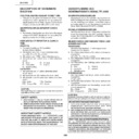
RS-232C Terminal: 9-pin Mini DIN female connector
Pin No.
Signal
Name
I/O
Reference
1
Output
Not connected
2
RD
Receive Data
Input
Connected to internal circuit
3
SD
Send Data
Output
Connected to internal circuit
4
Input
Not connected
5
SG
Signal Ground
Connected to internal circuit
6
Input
Not connected
7
RS
Request to Send
Output
Not connected
8
CS
Clear to Send
Input
Not connected
9
Output
Not connected
9-pin D-sub male connector of the DIN-D-sub RS-232C adaptor
Pin No.
Signal
Name
I/O
Reference
1
Not connected
2
RD
Receive Data
Input
Connected to internal circuit
3
SD
Send Data
Output
Connected to internal circuit
4
Not connected
5
SG
Signal Ground
Connected to internal circuit
6
Not connected
7
Output
Not connected
8
Input
Not connected
9
Not connected
RS-232C Cable recommended connection: 9-pin D-sub female connector
Pin No.
Signal
Pin No.
Signal
1
CD
CD
2
RD
RD
3
SD
SD
4
ER
ER
5
SG
SG
6
DR
DR
7
RS
RS
8
CS
CS
9
CI
CI
Note
•
INPUT 1/2 RGB and OUTPUT Signal Terminal: 15-pin Mini D-sub female connector
RGB Input
1. Video input (red)
2. Video input (green/sync on green)
3. Video input (blue)
4. Reserve input 1
5. Not connected
6. Earth (red)
7. Earth (green/sync on green)
8. Earth (blue)
9. Not connected
2. Video input (green/sync on green)
3. Video input (blue)
4. Reserve input 1
5. Not connected
6. Earth (red)
7. Earth (green/sync on green)
8. Earth (blue)
9. Not connected
10. GND
11. GND
12. Bi-directional data
13. Horizontal sync signal (Composite sync)
14. Vertical sync signal
15. Data clock
11. GND
12. Bi-directional data
13. Horizontal sync signal (Composite sync)
14. Vertical sync signal
15. Data clock
Component Input
1. P
R
(C
R
)
2. Y
3. P
3. P
B
(C
B
)
4. Not connected
5. Not connected
6. Earth (P
5. Not connected
6. Earth (P
R
)
7. Earth (Y)
8. Earth (P
8. Earth (P
B
)
9. Not connected
10. Not connected
11. Not connected
12. Not connected
13. Not connected
14. Not connected
15. Not connected
11. Not connected
12. Not connected
13. Not connected
14. Not connected
15. Not connected
Projector
Pin No.
4
5
6
5
6
PC
Pin No.
4
5
6
5
6
5
10
15
15
1
6
11
6
11
8
9
6
5
2
1
4
3
7
1
5
6
9
5
1
9
6
1
2
3
4
5
6
7
8
9
2
3
4
5
6
7
8
9
Display

