Sharp XG-C55X (serv.man10) Service Manual ▷ View online
16
XG-C55X
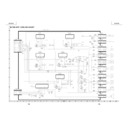
THE OPTICAL UNIT OUTLINE
Layout for proper setup of the optical components and parts (top view)
Projection Lens
Relay lens3
Relay lens 2
Relay lens 1
M5 AL-coated mirror B
M4 AL-coated mirror R
Fly-eye lens (Output)
L2
L2
L1
M3
B reflector
G reflector
R reflector
M2
Fly-eye lens (Input)
Light source (Lamp)
17
XG-C55X
Adjusting the mirrors
This adjustment is needed when any of the optical parts of the optical mechanism has been replaced.
1. Disconnect the flat cables from all the LCD panels.
2. Light up the lamp.
3. Project a white-light image and check to see if there is any color tint in any direction. If any, use the M2, M4 and M5
1. Disconnect the flat cables from all the LCD panels.
2. Light up the lamp.
3. Project a white-light image and check to see if there is any color tint in any direction. If any, use the M2, M4 and M5
adjusting levers.
4. Loosen the adjusting lever lock screws, make adjustments, and tighten up the lock screws.
Correcting color irregularities on white-only screen when replacing the lamp
If color irregularities are found at the right and left on a white-only screen after replacing the lamp, it is necessary to
readjust the optical axis of the new lamp. Take the following steps.
1. Open the lamp cover and loosen the screws A and B at the top of the lamp.
2. Using a screwdriver or the like, move the lever D in the arrow direction.
3. Temporarily fix the screws A and B, close the lamp cover, and check the white-only screen again for color
irregularities.
4. Repeat the above steps 1 and 2 until there will be no color irregularities. Now tighten up the screws A and B.
5. Finally secure the lamp cover back in position.
5. Finally secure the lamp cover back in position.
M4 Adjusting lever
M2 Adjusting lever
Lever D
Screw B
Screw A
Lock screws
Lock screws
Lock screws
M5 Adjusting lever
18
XG-C55X
Replacing the prism unit
1. Remove the four lock screws, and take the prism holder unit out of the optical unit.
2. Replace the prism unit with new one. Take the above step 1 in reverse order.
2. Replace the prism unit with new one. Take the above step 1 in reverse order.
Note: Even if just one of the LCD panels is defective, it is necessary to replace the entire prism unit. Do not replace
just the defective LCD panel only. Under the present circumstances, please do not touch the display part of
LCD.
LCD.
G-LCD panel
Optical unit
R-LCD panel
Prism unit lock screws
B-LCD panel
19
XG-C55X
How to Release the System Lock
order.
MENU → ENTER → ENTER → MENU → UNDO → UNDO → MENU
After pressing the MENU key first, press the remaining six keys within 10 seconds.
Display


