Sharp AR-M550 (serv.man14) Service Manual ▷ View online
AR-M550/M620 SETTING AND ADJUSTMENTS 7 - 3
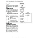
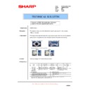
3) Go through the modes specified in Simulation 8-2.
4) Select the number that corresponds to the adjustment item using
the numeric keypad.
5) Press the Start key.
6) Press the start key to have the voltage output for 30 seconds.
The operation can be stopped with the CUSTOM SETTINGS key.
If the output voltage is not within the requirement, do the following
steps.
steps.
7) Enter the adjustment value using the numeric keypad.
8) Press the Start key
(The adjustment value is put into memory, and the corresponding
voltage is output for 30 seconds.)
voltage is output for 30 seconds.)
Repeat steps 7 to 8 until the output requirement is satisfied.
This adjustment is needed in the following situations:
• The high voltage power PWB (MC/DV/TC) has been replaced.
• U2 trouble has occurred.
• The PCU PWB has been replaced.
• The EEPROM of the PCU PWB has been replaced.
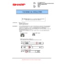
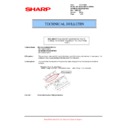
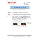
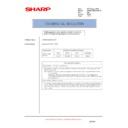
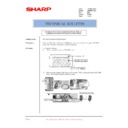
(Main charger grid voltage adjustment)
1) Remove the rear cover of the machine.
2) Apply a digital multi-meter to the connector CN2 pin (7) of the high
voltage PWB and the chassis GND.
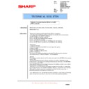
3) Go through the modes specified in Simulation 8-1.
Press [START] key.
Press [CUSTOM SETTINGS] key.
Press [START] key.
Press [CUSTOM SETTINGS] key.
Or after 30sec output.
Or after 30sec output.
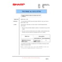
SIMULATION 8-2
1
MAIN GRID SETTING. SELECT 1-6, AND PRESS START.
1.AUTO
580
2.CHARACTER
580
3.MIX
580
4.PHOTO
580
5.PRINTER
580
6.FAX
580
SIMULATION 8-2
MAIN GRID SETTING. INPUT VALUE, AND PRESS START.
1.AUTO (200-1000)
580
SIMULATION 8-2
MAIN GRID SETTING. EXECUTING···.
1.AUTO
580
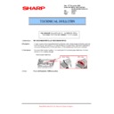
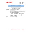
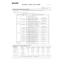
ADJ 1B
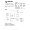
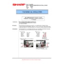
Adjust the developing bias voltage
Item/operation mode
Simulation
High voltage power PWB (MC/DV/TC)
Setting range
Default
Adjustment voltage
(monitor voltage)
Connector
Pin #
Actual
voltage
Copy
Auto mode
8-1
AUTO
0 – 750
495
–500±5v
CN2
7
–500±5v
Text mode
CHARACTER
0 – 750
495
–500±5v
CN2
7
–500±5v
Text/photo mode
MIX
0 – 750
495
–500±5v
CN2
7
–500±5v
Photo mode
PHOTO
0 – 750
495
–500±5v
CN2
7
–500±5v
Printer
All modes
PRINTER
0 – 750
495
–500±5v
CN2
7
–500±5v
FAX
All modes
FAX
0 – 750
495
–500±5v
CN2
7
–500±5v
Cleaning mode
PLUS
0 – 250
150
+150±5v
CN2
7
+150±5v
CN2
7
Press [START] key.
Press [CUSTOM SETTINGS] key.
Press [START] key.
Press [CUSTOM SETTINGS] key.
Or after 30sec output.
Or after 30sec output.
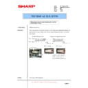
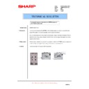
SIMULATION 8-1
1
DV BIAS SETTING. SELECT 1-7, AND PRESS START.
1.AUTO
495
2.CHARACTER
495
3.MIX
495
4.PHOTO
495
5.PRINTER
495
6.FAX
495
7.PLUS
150
SIMULATION 8-1
DV BIAS SETTING. INPUT VALUE, AND PRESS START.
1:AUTO (0-750)
495
SIMULATION 8-1
DV BIAS SETTING. EXECUTING···.
1:AUTO
495
AR-M550/M620 SETTING AND ADJUSTMENTS 7 - 4
4) Select the number that corresponds to the adjustment item using
the numeric keypad.
5) Press the Start key.
6) Press the start key to have the voltage output for 30 seconds.
The operation can be stopped with the CUSTOM SETTINGS key.
If the output voltage is not within the requirement, do the following
steps.
steps.
7) Enter the adjustment value using the numeric keypad.
8) Press the Start key
(The adjustment value is put into memory, and the corresponding
voltage is output for 30 seconds.)
voltage is output for 30 seconds.)
Repeat steps 7 to 8 until the output requirement is satisfied.
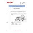
(Transfer voltage adjustment)
Transfer voltage adjustment (print operation mode)
This adjustment is needed in the following situations:
• The high voltage power PWB (MC/DV/TC) has been replaced.
• U2 trouble has occurred.
• The PCU PWB has been replaced.
• The EEPROM of the PCU PWB has been replaced.
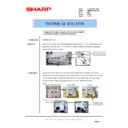
1) Go through the modes specified in Simulation 8-6.
2) Select the number that corresponds to the adjustment item
(FRONT/BACK) using the numeric keypad.
3) Press the Start key
4) Enter the adjustment value (default) using the numeric keypad.
5) Press the Start key
(The adjustment value is put into memory, and the corresponding
voltage is output for 30 seconds.)
voltage is output for 30 seconds.)
The operation can be stopped with the CUSTOM SETTINGS key.
Note: It is not possible to determine the adjusted transfer voltage
(print operation mode) (FRONT/BACK). If the voltage seems to
be abnormal after setting the default value, therefore, the high
voltage PWB (MC/DV/TC) should be replaced.
be abnormal after setting the default value, therefore, the high
voltage PWB (MC/DV/TC) should be replaced.
Transfer voltage adjustment (transfer belt cleaning mode)
This adjustment is needed in the following situations:
• The high voltage power PWB (MC/DV/TC) has been replaced.
• U2 trouble has occurred.
• The PCU PWB has been replaced.
• The EEPROM of the PCU PWB has been replaced.
1) Remove the rear cover of the machine.
2) Apply a digital multi-meter to the connector CN2 pin (1) of the high
voltage PWB and the chassis GND.
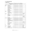
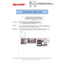
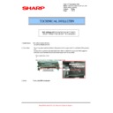
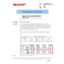
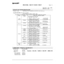
ADJ 1C
Adjust the transfer voltage
Item/operation
mode
Simulation
Adjustment voltage
(monitor voltage)
Connector
Pin #
Actual voltage/actual
current
Setting range
Default
Front print
8-6
FRONT
0 – 800
350
–
–
–
2.0 – 2.5Kv (35±1.0
µ
A)
High voltage
power PWB
(MC/DV/TC)
power PWB
(MC/DV/TC)
Back print
BACK
0 – 800
350
–
–
–
2.0 – 2.5Kv (35±1.0
µ
A)
Transfer belt
(cleaning)
(cleaning)
8-17
SHF FRONT
0 – 600
450
–
–
–
AC4.5Kv (p-p)
SHF BACK
0 – 600
450
–
–
–
AC4.5Kv (p-p)
THV-
0 – 75
10
DC -100±10v
CN2
1
DC -300±10v /
AC4.5Kv (p-p)
Transfer roller
(cleaning)
(cleaning)
8-18
CRHV PLUS
0 – 250
200
+2.0±0.1v
–
Check pin +2000±100v
High voltage
power PWB
(TC cleaning)
power PWB
(TC cleaning)
Transfer roller
(print)
(print)
CRHV MINUS
0 – 250
200
–2.0±0.1v
–
Check pin –2000±100v
Press [START] key.
Press [CUSTOM SETTINGS] key.
Press [START] key.
Press [CUSTOM SETTINGS] key.
Or after 30sec output.
Or after 30sec output.
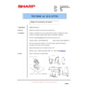
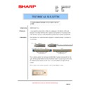
SIMULATION 8-6
1
THV+ SETTING. SELECT 1-2, AND PRESS START.
1.FRONT
350
2.BACK
350
SIMULATION 8-6
THV+ SETTING. INPUT VALUE, AND PRESS START.
1.FRONT(0-800)
350
SIMULATION 8-6
THV+ SETTING. EXECUTING···.
1.FRONT
350
CN2
1
AR-M550/M620 SETTING AND ADJUSTMENTS 7 - 5
3) Go through the modes specified in Simulation 8-17.
4) Select the number that corresponds to the adjustment item (SHF
FRONT / SHF BACK) using the numeric keypad.
5) Press the Start key.
6) Set each adjustment item to the default value (enter the adjust-
ment value and then press the Start key).
Note: The adjustment items (SHF FRONT / SHF BACK) correspond
to the AC component of the 'transfer belt cleaning mode voltage'
applied to the transfer roller, but this voltage component cannot
be determined. If the voltage seems to be abnormal after setting
the default adjustment value, therefore, the high voltage PWB
(MC/DV/TC) should be replaced.
applied to the transfer roller, but this voltage component cannot
be determined. If the voltage seems to be abnormal after setting
the default adjustment value, therefore, the high voltage PWB
(MC/DV/TC) should be replaced.
7) Select the number that corresponds to cleaning operation mode
(THV-) using the numeric keypad.
Note: The adjustment items (THV-) corresponds to the DC component
of the 'transfer belt cleaning mode voltage' applied to the trans-
fer roller.
fer roller.
8) Press the Start key.
9) Press the Start key to have the voltage output for 30 seconds.
If the output voltage is not within the requirement, do the following
steps.
steps.
The operation can be stopped with the CUSTOM SETTINGS key.
10) Enter the adjustment value using the numeric keypad.
11) Press the Start key.
(The adjustment value is put into memory, and the corresponding
voltage is output for 30 seconds.)
voltage is output for 30 seconds.)
Repeat steps 10 to 11 until the output requirement is satisfied.
Transfer voltage adjustment (transfer roller cleaning/
transfer roller print modes)
transfer roller print modes)
This adjustment is needed in the following situations:
• The high voltage power PWB (TC cleaning) has been replaced.
• U2 trouble has occurred.
• The PCU PWB has been replaced.
• The EEPROM of the PCU PWB has been replaced.
1) Connect the transfer section to the main body side using the trans-
fer extension harness (DHAi-3629FCZZ).
2) Remove the front frame cover of the duplex section, and remove
the rear frame cover of the transfer section.
3) Apply a digital multi-meter to the check pin of the high voltage
PWB (TC cleaning) and the chassis GND.
Press [START] key.
Press [CUSTOM SETTINGS] key.
Press [START] key.
Press [CUSTOM SETTINGS] key.
Or after 30sec output.
Or after 30sec output.
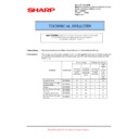
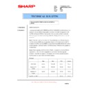
SIMULATION 8-17
1
TRANSFER ROLLER SETTING. SELECT 1-3, AND PRESS START.
1.SHV FRONT
450
2.SHV BACK
450
3.THV-
30
SIMULATION 8-17
TRANSFER ROLLER SETTING. INPUT VALUE, AND PRESS START.
1.FRONT (0-600)
450
SIMULATION 8-17
TRANSFER ROLLER SETTING. EXECUTING···.
1.FRONT(0-600)
450
AR-M550/M620 SETTING AND ADJUSTMENTS 7 - 6
4) Go through the modes specified in Simulation 8-18.
5) Select the number that corresponds to the adjustment item (CRHV
PLUS / CRHV MINUS) using the numeric keypad.
6) Press the Start key
7) Press the Start key to have the voltage output for 30 seconds.
The operation can be stopped with the CUSTOM SETTINGS key.
If the output voltage is not within the requirement, do the following
steps.
steps.
8) Enter the adjustment value using the numeric keypad.
9) Press the Start key.
(The adjustment value is put into memory, and the corresponding
voltage is output for 30 seconds.)
voltage is output for 30 seconds.)
Repeat steps 8 to 9 until the output requirement is satisfied.
This adjustment is needed in the following situations:
• The developing unit has been disassembled.
• The print density is low.
• The toner is excessively dispersed.
1) Remove the developing unit of the machine.
2) Remove the developing unit cover and blade cover.
3) Loosen the DV doctor fixing screws.
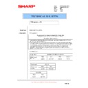
4) Manually turn the DV roller to align the marking on the DV roller
surface with the DV doctor position.
5) Insert a 0.525mm clearance gauge in between the DV roller and
DV doctor so that the gauge is positioned at a distance of 40 mm to
70 mm from the DV doctor end face.
70 mm from the DV doctor end face.
6) Tighten the DV doctor fixing screws while pressing the DV doctor
in the arrow direction.
(This should be done for both front and rear frames.)
(This should be done for both front and rear frames.)
Press [START] key.
Press [CUSTOM SETTINGS] key.
Press [START] key.
Press [CUSTOM SETTINGS] key.
Or after 30sec output.
Or after 30sec output.
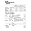
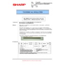
ADJ 2
Adjusting the developing unit
ADJ 2A
Adjust the developing doctor gap
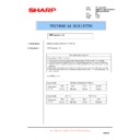
SIMULATION 8-18
1
TRANSFER CLEANING ROLLER SETTING. SELECT 1-2, AND
PRESS START.
1.CRHV PLUS
50
2.CRHV MINUS
50
SIMULATION 8-18
TRANSFER CLEANING ROLLER SETTING. INPUT VALUE, AND
PRESS START.
1.CRHV PLUS (0-250)
200
SIMULATION 8-18
TRANSFER CLEANING ROLLER SETTING. EXECUTING···.
1.CRHV PLUS(0-250)
200

