|
MX-6240N MX-7040N
MX6540N- MX7040N PCL6 PS PPD Printer-Driver Win32 GB PCL6 Postscript PPD Printer-Driver for Windows XP, Windows Vista, Windows 7, Windows 8, Windows Server 2003, Windows Server 2008 with WHQL, version 1302a, production run date 29 03 2013, English language
-Document-
|
|
211.63 MB
|

|
MX-6240N MX-7040N (serv.man2)
MX7040N PCL6 PS PPD Printer-Driver Win32 GB PCL6 Postscript PPD Printer-Driver for Windows XP, Windows Vista, Windows 7, Windows 8, Windows Server 2003, Windows Server 2008, version 1211a, production run date 30 11 2012, English language
-Document-
|
|
21.11 MB
|

|
MX-6240N MX-7040N (serv.man3)
MX6240 7040N PCL6 and PS Printer Driver for Windows 2000, XP, Vista, 7 and Server 2003, 2008 (32 Bit)
-Document-
|
|
20.84 MB
|

|
MX-6240N MX-7040N (serv.man4)
MX7040N PCL6 PS PPD Printer-Driver Win64 GB PCL6 PS PPD Printer-Driver for Windows XP x64, Windows Vista x64, Windows 7 x64, Windows 8 x64, Windows Server 2003 x64, Windows Server 2008 x64, Windows Server 2008 R2, Windows Server 2012, version 1211a, production run date 30 11 2012, English language
-Document-
|
|
22.15 MB
|

|
MX-6240N MX-7040N (serv.man5)
MX6240 7040N PCL6 and PS Printer Driver for Windows XP, Vista, 7 and Server 2003, 2008 (64 Bit)
-Document-
|
|
21.92 MB
|

|
MX-6240N MX-7040N (serv.man6)
Mac OS10.8 Driver Rquires Postscript option.
-Document-
|
|
1.56 MB
|
|
|
MX-CF11 MX-6240N MX-7040N (serv.man2)
Updated March 2013
Service Manual
|
127
|
43.31 MB
|
|
|
MX-6240N MX-7040N (serv.man16)
Installation Manual (Revised May 2017).
Service Manual
|
127
|
45.15 MB
|
|
|
MX-6240N MX-7040N (serv.man17)
Service Manual (Revised May 2017).
Service Manual
|
127
|
79.03 MB
|
|
|
MX-6240N MX-7040N (serv.man18)
Covers - Updated November 2012
Service Manual
|
5
|
3.21 MB
|
|
|
MX-6240N MX-7040N (serv.man19)
Note for Servicing - Updated November 2012
Service Manual
|
3
|
241.27 KB
|
|
|
MX-6240N MX-7040N (serv.man20)
Section 1 Product Outline - Updated November 2012
Service Manual
|
3
|
338.69 KB
|
|
|
MX-6240N MX-7040N (serv.man21)
Section 2 Specifications - Updated November 2012
Service Manual
|
13
|
224.4 KB
|
|
|
MX-6240N MX-7040N (serv.man22)
Section 3 Consumable Parts - Updated November 2012
Service Manual
|
7
|
227.55 KB
|
|
|
MX-6240N MX-7040N (serv.man23)
Section 4 External view and Internal Structure - Updated November 2012
Service Manual
|
26
|
3.75 MB
|
|
|
MX-6240N MX-7040N (serv.man24)
Section 5 Adjustments and Settings - Updated November 2012
Service Manual
|
99
|
5.76 MB
|
|
|
MX-6240N MX-7040N (serv.man25)
Section 6 Simulation - Updated November 2012
Service Manual
|
127
|
2.38 MB
|
|
|
MX-6240N MX-7040N (serv.man26)
Section 7 Troubleshooting - Updated November 2012
Service Manual
|
69
|
603.72 KB
|
|
|
MX-6240N MX-7040N (serv.man27)
Section 8 Firmware Update - Updated November 2012
Service Manual
|
5
|
682.5 KB
|
|
|
MX-6240N MX-7040N (serv.man28)
Section 9 Maintenance - Updated November 2012
Service Manual
|
27
|
4.89 MB
|
|
|
MX-6240N MX-7040N (serv.man29)
Section 10 Disassembly and assembly - Updated November 2012
Service Manual
|
72
|
48.94 MB
|
|
|
MX-6240N MX-7040N (serv.man30)
Section 11 Various Storage Data Handling - Updated November 2012
Service Manual
|
18
|
457.96 KB
|
|
|
MX-6240N MX-7040N (serv.man31)
Section 12 Service Web page - Updated November 2012
Service Manual
|
5
|
3.91 MB
|
|
|
MX-6240N MX-7040N (serv.man32)
Section 13 Operational Descriptions - Updated November 2012
Service Manual
|
49
|
6.45 MB
|
|
|
MX-6240N MX-7040N (serv.man33)
Section 14 Electrical Section - Updated November 2012
Service Manual
|
38
|
708.97 KB
|
|
|
MX-6240N MX-7040N (serv.man34)
Circuit Diagram
Service Manual
|
127
|
11.23 MB
|
|
|
MX-CF11
Service Manual
Service Manual
|
23
|
2.23 MB
|

|
MX-6240N MX-7040N (serv.man37)
e-Manual Ver 01.30
User Manual / Operation Manual
|
|
737.74 MB
|
|
|
MX-CF11 MX-6240N MX-7040N (serv.man4)
Revised February 2013
Service Manual / Parts Guide
|
33
|
3.83 MB
|
|
|
MX-CF11 MX-6240N MX-7040N (serv.man5)
July 2012
Service Manual / Parts Guide
|
33
|
3.73 MB
|
|
|
MX-6240N MX-7040N (serv.man35)
Parts Guide includes MF10, LT10, EB15, KB13, TU14 TR14 (Revised November 2016).
Service Manual / Parts Guide
|
127
|
105.79 MB
|
|
|
MX-6240N MX-7040N (serv.man36)
Revised April 2013
Service Manual / Parts Guide
|
54
|
992.9 KB
|
|
|
MX-CF11 (serv.man2)
New Parts Guide
Service Manual / Parts Guide
|
33
|
3.84 MB
|
|
|
MX-CF11 MX-6240N MX-7040N
All Sections
Service Manual / Specification
|
23
|
2.23 MB
|
|
|
MX-6240N MX-7040N (serv.man14)
Sharp Media Guide
Service Manual / Specification
|
54
|
2.6 MB
|
|
|
MX-6240N MX-7040N (serv.man15)
General Product Specifications, (taken from Service Manual)
Service Manual / Specification
|
13
|
224.42 KB
|
|
|
MX-6240N MX-7040N (serv.man50)
CCE1848-PARTS MODIFICATION FOR COMMON USE WITH OTHER MODELS, ADU REVERSE GUIDE AND PAWLS
Service Manual / Technical Bulletin
|
3
|
245.29 KB
|
|
|
MX-6240N MX-7040N (serv.man51)
Change of Connector (Revision)
Service Manual / Technical Bulletin
|
5
|
350.94 KB
|
|
|
MX-6240N MX-7040N (serv.man52)
CCE1832-PARTS CHANGE FOR COMMON USE WITH OTHER MODELS
Service Manual / Technical Bulletin
|
7
|
558.71 KB
|
|
|
MX-6240N MX-7040N (serv.man53)
CCE1820-PARTS CHANGE FOR COMMON USE WITH OTHER MODELS
Service Manual / Technical Bulletin
|
4
|
377.94 KB
|
|
|
MX-6240N MX-7040N (serv.man54)
CCE1815-PARTS CHANGE FOR COMMON USE WITH OTHER MODELS
Service Manual / Technical Bulletin
|
2
|
266.45 KB
|
|
|
MX-6240N MX-7040N (serv.man55)
CCE1814-PARTS CHANGE FOR COMMON USE WITH OTHER MODELS
Service Manual / Technical Bulletin
|
5
|
360.2 KB
|
|
|
MX-6240N MX-7040N (serv.man56)
CCE-1829 MODIFICATION OF PARTS DESIGN
Service Manual / Technical Bulletin
|
2
|
305 KB
|
|
|
MX-6240N MX-7040N (serv.man57)
Parts change for productivity improvement.
Service Manual / Technical Bulletin
|
3
|
184.15 KB
|
|
|
MX-6240N MX-7040N (serv.man58)
PARTS CHANGE FOR COMMON USE WITH OTHER MODELS
Service Manual / Technical Bulletin
|
2
|
244 KB
|
|
|
MX-6240N MX-7040N (serv.man59)
DESIGN CHANGE OF MF TRANSPORT PG
Service Manual / Technical Bulletin
|
2
|
249.36 KB
|
|
|
MX-6240N MX-7040N (serv.man60)
CCE 1785 DISCONTINUATION OF SUPPLY OF LAMP BASE
Service Manual / Technical Bulletin
|
4
|
400.71 KB
|
|
|
MX-6240N MX-7040N (serv.man61)
MODIFICATION OF DEVELOPER FILTER HOLDER UNIT
Service Manual / Technical Bulletin
|
2
|
209.53 KB
|
|
|
MX-6240N MX-7040N (serv.man62)
DESIGN CHANGE OF FUSING CENTER PAPER GUIDE
Service Manual / Technical Bulletin
|
2
|
301.38 KB
|
|
|
MX-6240N MX-7040N (serv.man63)
ADU PARTS CHANGE FOR COMMON USE WITH OTHER MODELS
Service Manual / Technical Bulletin
|
2
|
228.93 KB
|
|
|
MX-6240N MX-7040N (serv.man64)
CHANGE OF SD CARD
Service Manual / Technical Bulletin
|
3
|
287.22 KB
|
|
|
MX-6240N MX-7040N (serv.man65)
MODIFICATION OF DELIVERY UNIT
Service Manual / Technical Bulletin
|
2
|
368.31 KB
|
|
|
MX-6240N MX-7040N (serv.man66)
SERVICE PARTS SET UP FOR RB14 ADU TRANSPORT UNIT
Service Manual / Technical Bulletin
|
2
|
264.91 KB
|
|
|
MX-6240N MX-7040N (serv.man67)
CHANGE OF MC FAN DUCT
Service Manual / Technical Bulletin
|
2
|
273.53 KB
|
|
|
MX-6240N MX-7040N (serv.man68)
CCE-1701 Change of SD card
Service Manual / Technical Bulletin
|
2
|
165.68 KB
|
|
|
MX-6240N MX-7040N (serv.man69)
QTY CHANGE OF DUMPER SPRING OF DR POSITIONING UNIT
Service Manual / Technical Bulletin
|
2
|
422.3 KB
|
|
|
MX-6240N MX-7040N (serv.man70)
PARTS CHANGE OF PROCESS UNIT
Service Manual / Technical Bulletin
|
3
|
428.6 KB
|
|
|
MX-6240N MX-7040N (serv.man71)
PARTS MODIFICATION FOR COMMON USE WITH OTHER MODELS
Service Manual / Technical Bulletin
|
5
|
258.75 KB
|
|
|
MX-6240N MX-7040N (serv.man72)
CHANGE OF PARTS (FUSER FRAME) FOR COMMON USE WITH OTHER MODELS
Service Manual / Technical Bulletin
|
3
|
289.33 KB
|
|
|
MX-6240N MX-7040N (serv.man73)
PARTS CHANGE DUE TO COMMONALITY WITH NEW PRODUCT
Service Manual / Technical Bulletin
|
2
|
555.35 KB
|
|
|
MX-6240N MX-7040N (serv.man74)
Enhancement of LC13 Main Drive Gear
Service Manual / Technical Bulletin
|
3
|
760.63 KB
|
|
|
MX-6240N MX-7040N (serv.man75)
CHANGE OF MX-RB14 HINGE AND HINGE HOLDER
Service Manual / Technical Bulletin
|
2
|
135.92 KB
|
|
|
MX-6240N MX-7040N (serv.man76)
Change of PPD5 interface harness.
Service Manual / Technical Bulletin
|
2
|
108.01 KB
|
|
|
MX-6240N MX-7040N (serv.man77)
IMPROVEMENT FOR CONTAMINATION OF FOREIGN MATERIAL INTO FUSING ROLLER BEARING
Service Manual / Technical Bulletin
|
2
|
90.97 KB
|
|
|
MX-6240N MX-7040N (serv.man78)
NOISE AT FUSING DRIVE SECTION
Service Manual / Technical Bulletin
|
2
|
205.08 KB
|
|
|
MX-6240N MX-7040N (serv.man79)
CHANGE OF STANDARD FIXING POSITION OF FUSING FRONT LOWER PG
Service Manual / Technical Bulletin
|
1
|
128.21 KB
|
|
|
MX-6240N MX-7040N (serv.man80)
IMPROVEMENT FOR FLYWHEEL COMING OFF
Service Manual / Technical Bulletin
|
2
|
45.69 KB
|
|
|
MX-6240N MX-7040N (serv.man81)
IMPROVEMENT OF IMAGE QUALITY ON HEAVY PAPER
Service Manual / Technical Bulletin
|
3
|
163.33 KB
|
|
|
MX-6240N MX-7040N (serv.man82)
ENHANCEMENT FOR PREVENTION OF DAMAGE ON HEAT ROLLER (2)
Service Manual / Technical Bulletin
|
3
|
172.99 KB
|
|
|
MX-6240N MX-7040N (serv.man83)
Notification of CPO (License Manager) and support for SHA-2.
Service Manual / Technical Bulletin
|
3
|
38.6 KB
|
|
|
MX-6240N MX-7040N (serv.man84)
CCE 1508 IMPROVEMENT OF PERFORMANCE WHEN OPENING CLOSING DSPF LOWER DOOR
Service Manual / Technical Bulletin
|
3
|
235.02 KB
|
|
|
MX-6240N MX-7040N (serv.man85)
Design change of delivery paper guide.
Service Manual / Technical Bulletin
|
2
|
91.45 KB
|
|
|
MX-6240N MX-7040N (serv.man86)
Change in shape of open close lock pawl.
Service Manual / Technical Bulletin
|
3
|
97.28 KB
|
|
|
MX-6240N MX-7040N (serv.man87)
CHANGE IN COLOUR OF PIPE CUSHION
Service Manual / Technical Bulletin
|
2
|
60.13 KB
|
|
|
MX-6240N MX-7040N (serv.man88)
REMEDY FOR FLIPPING 1ST TRANSFER CLEANING BLADE
Service Manual / Technical Bulletin
|
2
|
376.75 KB
|
|
|
MX-6240N MX-7040N (serv.man89)
Starting Powder List (This list takes priority over information in Service Manuals).
Service Manual / Technical Bulletin
|
4
|
66.25 KB
|
|
|
MX-6240N MX-7040N (serv.man90)
CAUTION ILLUSTRATIONS ADDED TO PACKING BOX.
Service Manual / Technical Bulletin
|
1
|
83.72 KB
|
|
|
MX-6240N MX-7040N (serv.man91)
MX-FR36U ROM UPGRADE ..... (4). Ver 05.10.Sc
Service Manual / Technical Bulletin
|
3
|
34.26 KB
|
|
|
MX-6240N MX-7040N (serv.man92)
ROM UPGRADE ..... (9). Ver 05.00.S1
Service Manual / Technical Bulletin
|
3
|
42.18 KB
|
|
|
MX-6240N MX-7040N (serv.man93)
REMEDY FOR TOOTH SKIPPING OF DV BELT
Service Manual / Technical Bulletin
|
3
|
340.09 KB
|
|
|
MX-6240N MX-7040N (serv.man94)
IMPROVEMENT FOR LOOSENING OF SCREWS FIXING FUSING REAR LOWER PG STAY AND FUSING REAR LOWER PG
Service Manual / Technical Bulletin
|
2
|
136.27 KB
|
|
|
MX-6240N MX-7040N (serv.man95)
COUNTERMEASURE FOR PAPER JAM (POD1 ETC.) TRIGGERED BY DECREASE IN HARDNESS OF FUSING ROLLER
Service Manual / Technical Bulletin
|
2
|
253.49 KB
|
|
|
MX-6240N MX-7040N (serv.man96)
COUNTERMEASURE FOR NOISE BY CLEARANCE OF JOINT SECTION BETWEEN DRIVE GEAR AND PARALLEL PIN
Service Manual / Technical Bulletin
|
1
|
76.27 KB
|
|
|
MX-6240N MX-7040N (serv.man97)
ROM UPGRADE ..... (8). Ver 04.01S1
Service Manual / Technical Bulletin
|
6
|
342.22 KB
|
|
|
MX-6240N MX-7040N (serv.man98)
COUNTERMEASURE FOR FUSER NOISE DUE TO ABRASION TO THE DRIVE GEAR 24T
Service Manual / Technical Bulletin
|
2
|
364.13 KB
|
|
|
MX-6240N MX-7040N (serv.man99)
CCE 1389R COUNTERMEASURE FOR E7-11 TROUBLE
Service Manual / Technical Bulletin
|
3
|
278.04 KB
|
|
|
MX-6240N MX-7040N (serv.man100)
NEWLY-REGISTERED SERVICE PARTS FOR FINSHERS
Service Manual / Technical Bulletin
|
5
|
931.93 KB
|
|
|
MX-6240N MX-7040N (serv.man101)
SETUP OF NEW SERVICE PARTS - PROCESS UNIT
Service Manual / Technical Bulletin
|
3
|
549.61 KB
|
|
|
MX-6240N MX-7040N (serv.man102)
Recommended shutdown procedure and Power Cycling of MFD
Service Manual / Technical Bulletin
|
1
|
186.43 KB
|
|
|
MX-6240N MX-7040N (serv.man103)
IMPORTANT Handling of EEPROM's.
Service Manual / Technical Bulletin
|
5
|
203.32 KB
|
|
|
MX-6240N MX-7040N (serv.man104)
REMEDY FOR NON-UNIFORM COLOUR DENSITY IN UNEVEN PITCH, TONER DISPERSION AND FLIPPING OF PRIMARY TRANSFER CLEANING BLADE
Service Manual / Technical Bulletin
|
5
|
827.15 KB
|
|
|
MX-6240N MX-7040N (serv.man105)
MODIFICATION OF NOISE GENERATED BY CONTACT BETWEEN TENSION PLATE AND DRIVE TRANSPORT FRAME.
Service Manual / Technical Bulletin
|
2
|
208.65 KB
|
|
|
MX-6240N MX-7040N (serv.man106)
Countermeasure for E7-11 trouble.
Service Manual / Technical Bulletin
|
3
|
125.27 KB
|
|
|
MX-6240N MX-7040N (serv.man107)
MODIFICATION OF PARTS IN FUSING DRIVE UNIT FOR COMMON USE WITH OTHER MODELS
Service Manual / Technical Bulletin
|
3
|
371.21 KB
|
|
|
MX-6240N MX-7040N (serv.man108)
CHANGE OF SHAPE FUSING REAR LOWER PAPER GUIDE COVER
Service Manual / Technical Bulletin
|
2
|
181.09 KB
|
|
|
MX-6240N MX-7040N (serv.man109)
COUNTERMEASURE TO REDUCE OPERATING NOISE OF PAPER FEED SOLENOID
Service Manual / Technical Bulletin
|
2
|
102.4 KB
|
|
|
MX-6240N MX-7040N (serv.man110)
MODIFICATION OF PROCESS UNIT FOR UTILIZATION OF COMMON PARTS WITH OTHER MODELS
Service Manual / Technical Bulletin
|
2
|
145.6 KB
|
|
|
MX-6240N MX-7040N (serv.man111)
Countermeasures against contamination of paper surface.
Service Manual / Technical Bulletin
|
2
|
24.64 KB
|
|
|
MX-6240N MX-7040N (serv.man112)
CHANGE OF MANUFACTURER OF CCD FFC
Service Manual / Technical Bulletin
|
2
|
192.74 KB
|
|
|
MX-6240N MX-7040N (serv.man113)
MODIFICATION OF FLASH ROM FOR PRODUCTIVITY IMPROVEMENT AND PARTS COMMONIZATION
Service Manual / Technical Bulletin
|
2
|
156.9 KB
|
|
|
MX-6240N MX-7040N (serv.man114)
Modification of flash ROM for productivity improvement and parts communization
Service Manual / Technical Bulletin
|
2
|
285.53 KB
|
|
|
MX-6240N MX-7040N (serv.man115)
REMEDY FOR DEFECT IMAGES (VOID AREA) ON HEAVY PAPER AND GLOSS PAPER ETC.
Service Manual / Technical Bulletin
|
1
|
19.9 KB
|
|
|
MX-6240N MX-7040N (serv.man116)
IMPROVEMENT FOR FLYWHEEL COMING OFF
Service Manual / Technical Bulletin
|
2
|
108.46 KB
|
|
|
MX-6240N MX-7040N (serv.man117)
MX-FN22 Missing Front Staple on Double Staple Set.
Service Manual / Technical Bulletin
|
2
|
325.41 KB
|
|
|
MX-6240N MX-7040N (serv.man118)
A REMINDER TO TAKE EXTRA CARE WHILE DRAWING OUT AND INSERTING DV UNIT
Service Manual / Technical Bulletin
|
1
|
50.76 KB
|
|
|
MX-6240N MX-7040N (serv.man119)
ROM UPGRADE ..... (7). Ver 04.00.S100
Service Manual / Technical Bulletin
|
3
|
37.54 KB
|
|
|
MX-6240N MX-7040N (serv.man120)
NOISE CAUSED BY CONTACT BETWEEN FUSING F COVER AND C-RING
Service Manual / Technical Bulletin
|
1
|
34.19 KB
|
|
|
MX-6240N MX-7040N (serv.man121)
JAM (POD1N ETC) AT FUSING REAR UPPER SEPARATE PLATE SECTION
Service Manual / Technical Bulletin
|
1
|
20.52 KB
|
|
|
MX-6240N MX-7040N (serv.man122)
MX-FR36U DSK ROM UPGRADE ..... (3). Ver 04.10.Sc00
Service Manual / Technical Bulletin
|
3
|
32.61 KB
|
|
|
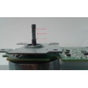
MX-6240N MX-7040N (serv.man123)
CHANGE OF PHOTO SENSOR
Service Manual / Technical Bulletin
|
2
|
111.52 KB
|
|
|
MX-6240N MX-7040N (serv.man124)
ELIMINATION OF LCD PROTECT MOLT OF 10.1 INCH OPERATION PANEL.
Service Manual / Technical Bulletin
|
2
|
180.25 KB
|
|
|
MX-6240N MX-7040N (serv.man125)
IMPROVEMENT OF DETECTION ACCURACY FOR DSPF TRANSPORT UPPER ACTUATOR.
Service Manual / Technical Bulletin
|
2
|
198.78 KB
|
|
|
MX-6240N MX-7040N (serv.man126)
CHANGE OF POWER SAVE SWITCH
Service Manual / Technical Bulletin
|
1
|
79.74 KB
|
|
|
MX-6240N MX-7040N (serv.man127)
COUNTERMEASURE FOR RIDING ON TO 1ST TENSIONER ROLLER DUE TO MEANDERING OF 1ST TRANSFER BELT
Service Manual / Technical Bulletin
|
2
|
242.09 KB
|
|
|
MX-6240N MX-7040N (serv.man128)
ENHANCEMENT OF FLAPPER, FEED, UPPER IN TRANSPORT SECTION (MX-RB12)
Service Manual / Technical Bulletin
|
2
|
125.45 KB
|
|
|
MX-6240N MX-7040N (serv.man129)
CAUTION FOR REPLACEMENT OF FUSING DRIVE SHAFT TO REDUCE NOISE
Service Manual / Technical Bulletin
|
1
|
123.15 KB
|
|
|
MX-6240N MX-7040N (serv.man130)
IMPLEMENTATION OF COUNTERMEASURE AGAINST PAPER WRINKLE DURING FINISHER INSTALLATION
Service Manual / Technical Bulletin
|
1
|
191.42 KB
|
|
|
MX-6240N MX-7040N (serv.man131)
COUNTERMEASURE FOR SKEW WHEN FEEDING INVOICE PAPER WITH DUPLEX
Service Manual / Technical Bulletin
|
2
|
282.5 KB
|
|
|
MX-6240N MX-7040N (serv.man132)
CAUTION WHEN EXECUTING SECONDARY TRANSFER MAINTENANCE
Service Manual / Technical Bulletin
|
1
|
65.02 KB
|
|
|
MX-6240N MX-7040N (serv.man133)
CHANGE IN THE SHAPE OF FUSING UNIT FIXING SCREW AND FUSING DRIVE PLATE R
Service Manual / Technical Bulletin
|
2
|
66.88 KB
|
|
|
MX-6240N MX-7040N (serv.man134)
IMPROVEMENT FOR WASTE TONER LEAKAGE
Service Manual / Technical Bulletin
|
2
|
237.22 KB
|
|
|
MX-6240N MX-7040N (serv.man135)
COUNTERMEASURE AGAINST MISALIGNMENT OF BEARING ON RIGHT PAPER EXIT ROLLER
Service Manual / Technical Bulletin
|
3
|
256.79 KB
|
|
|
MX-6240N MX-7040N (serv.man136)
ROM UPGRADE ..... (6). Ver ICU 03.01.S1, PCU 02.02.S1
Service Manual / Technical Bulletin
|
1
|
94.94 KB
|
|
|
MX-6240N MX-7040N (serv.man137)
COUNTERMEASURE FOR TONER CONTAMINATION ON RESIST PRO CON SENSOR
Service Manual / Technical Bulletin
|
2
|
268.78 KB
|
|
|
MX-6240N MX-7040N (serv.man138)
Enhancement of dust control for the scanner unit.
Service Manual / Technical Bulletin
|
2
|
61.05 KB
|
|
|
MX-6240N MX-7040N (serv.man139)
DSK ROM UPGRADE ..... (2). Ver 03.01Sc00
Service Manual / Technical Bulletin
|
4
|
197.9 KB
|
|
|
MX-6240N MX-7040N (serv.man140)
IMPROVEMENT FOR FLYWHEEL COMING OFF
Service Manual / Technical Bulletin
|
1
|
163.73 KB
|
|
|
MX-6240N MX-7040N (serv.man141)
CONVERTING THE MX-RB14 TO USE 19-INCH-SIZE PAPER
Service Manual / Technical Bulletin
|
2
|
352.65 KB
|
|
|
MX-6240N MX-7040N (serv.man142)
IMPROVEMENT FOR VOID DUE TO SLIPPERY COUPLING OF MAIN DRIVE
Service Manual / Technical Bulletin
|
2
|
145.07 KB
|
|
|
MX-6240N MX-7040N (serv.man143)
ROM UPGRADE ..... (5). Ver 03.00.S1
Service Manual / Technical Bulletin
|
4
|
136.26 KB
|
|
|
MX-6240N MX-7040N (serv.man144)
ROM UPGRADE ..... (4). Ver ICU 02.00.S1, PCU 02.01.S1
Service Manual / Technical Bulletin
|
1
|
91.35 KB
|
|
|
MX-6240N MX-7040N (serv.man145)
REMEDY FOR TONER DEVELOPER DISPERSION AT PROCESS UNIT SECTION
Service Manual / Technical Bulletin
|
5
|
1.42 MB
|
|
|
MX-6240N MX-7040N (serv.man146)
CHANGE OF PCU PWB FOR PRODUCTIVITY IMPROVEMENT
Service Manual / Technical Bulletin
|
2
|
526.2 KB
|
|
|
MX-6240N MX-7040N (serv.man147)
IMPROVEMENT FOR NOISE FROM FUSING DRIVE SECTION
Service Manual / Technical Bulletin
|
1
|
121.21 KB
|
|
|
MX-6240N MX-7040N (serv.man148)
ENHANCEMENT FOR DISLOCATION ISSUE OF TRANSPORT TOP ACTUATOR
Service Manual / Technical Bulletin
|
2
|
187.29 KB
|
|
|
MX-6240N MX-7040N (serv.man149)
PAY EXTRA ATTENTION FOR REUSABLE BAND OF DSPF INTERFACE HARNESS BECOMING UN-SECURED
Service Manual / Technical Bulletin
|
1
|
252.94 KB
|
|
|
MX-6240N MX-7040N (serv.man150)
COUNTERMEASURE AGAINST MISALIGNMENT OF BEARING ON RIGHT PAPER EXIT ROLLER
Service Manual / Technical Bulletin
|
1
|
295.08 KB
|
|
|
MX-6240N MX-7040N (serv.man151)
DISCONTINUATION OF GEAR AND E RINGS MOUNTED TO REAR SIDE OF FUSING UNIT
Service Manual / Technical Bulletin
|
1
|
188.06 KB
|
|
|
MX-6240N MX-7040N (serv.man152)
FIRMWARE UPGRADE ..... (2)Ver 01.08.S1
Service Manual / Technical Bulletin
|
1
|
83.59 KB
|
|
|
MX-6240N MX-7040N (serv.man153)
MX-FR36U - ROM UPGRADE ..... (1). Ver. 02.10.Sc.00
Service Manual / Technical Bulletin
|
3
|
109.54 KB
|
|
|
MX-6240N MX-7040N (serv.man154)
ROM UPGRADE (2) - (3) Ver 0200S100
Service Manual / Technical Bulletin
|
4
|
119.33 KB
|
|
|
MX-6240N MX-7040N (serv.man155)
CHANGE OF MANUAL REGISTRATION ADJUSTMENT PATTERN SIM50-20
Service Manual / Technical Bulletin
|
1
|
332.89 KB
|
|
|
MX-6240N MX-7040N (serv.man156)
ENHANCEMENT FOR PAPER FEED BELT DAMAGE OF AIR PAPER UNIT
Service Manual / Technical Bulletin
|
3
|
282.49 KB
|
|
|
MX-6240N MX-7040N (serv.man157)
COUNTERMEASURE AGAINST F0-10 ERROR ETC. DURING THE INITIAL OPERATION OF STAPLE
Service Manual / Technical Bulletin
|
2
|
233.82 KB
|
|
|
MX-6240N MX-7040N (serv.man158)
IMPROVEMENT FOR THE DAMAGE AT THE END OF FUSING BELT DUE TO MEANDERING
Service Manual / Technical Bulletin
|
3
|
1000.32 KB
|
|
|
MX-6240N MX-7040N (serv.man159)
MX-FN21 MX-FN22 ROM UPGRADE..... (1). Ver 01.09.01.a
Service Manual / Technical Bulletin
|
1
|
89.76 KB
|
|
|
MX-6240N MX-7040N (serv.man160)
FIRMWARE UPDATE FOR INSTALLATION OF MX-EB11
Service Manual / Technical Bulletin
|
1
|
85.73 KB
|
|
|
MX-6240N MX-7040N (serv.man161)
IMPROVEMENT FOR DIRT ON REAR EDGE OF PAPER
Service Manual / Technical Bulletin
|
1
|
159.59 KB
|
|
|
MX-6240N MX-7040N (serv.man162)
CCE-1067 Shape of the waste toner pipe D has been changed to improve operation.
Service Manual / Technical Bulletin
|
2
|
189.02 KB
|
|
|
MX-6240N MX-7040N (serv.man163)
EXTRA ATTENTION TO BE PAID WHEN ATTACHING TONER CARTRIDGES
Service Manual / Technical Bulletin
|
1
|
245.14 KB
|
|
|
MX-6240N MX-7040N (serv.man164)
NEW Toner near end adjustment changed.
Service Manual / Technical Bulletin
|
1
|
479.78 KB
|
|
|
MX-6240N MX-7040N (serv.man165)
CHANGE OF WASTE TONER TRANSPORT PIPE D IN SHAPE AND DISCONTINUED USE OF TONER PIPE MOLT FORM
Service Manual / Technical Bulletin
|
2
|
274.99 KB
|
|
|
MX-6240N MX-7040N (serv.man166)
CORRECTIVE ACTION FOR RUSTED BEARING OF DV UNIT
Service Manual / Technical Bulletin
|
3
|
364.2 KB
|
|
|
MX-6240N MX-7040N (serv.man167)
CHANGE OF DESCRIPTION ON FUSING PAPER GUIDE FIXING POSITION IN SERVICE MANUAL
Service Manual / Technical Bulletin
|
2
|
203.51 KB
|
|
|
MX-6240N MX-7040N (serv.man168)
MODIFICATION OF NOISE GENERATED FROM 2nd TRANSFER UNIT
Service Manual / Technical Bulletin
|
2
|
169.27 KB
|
|
|
MX-6240N MX-7040N (serv.man169)
ROM VERSION UPGRADE (1) - (2) Ver 0102S100
Service Manual / Technical Bulletin
|
2
|
94.67 KB
|
|
|
MX-6240N MX-7040N (serv.man170)
CAUTION WHEN ATTACHING DV COVER
Service Manual / Technical Bulletin
|
3
|
648 KB
|
|
|
MX-6240N MX-7040N (serv.man171)
DEVICE CLONING DIFFERENCES BETWEEN CR2 CR3 GENERATION MODELS
Service Manual / Technical Bulletin
|
2
|
58.53 KB
|
|
|
MX-6240N MX-7040N (serv.man172)
DEVICE CLONING
Service Manual / Technical Bulletin
|
2
|
126.14 KB
|
|
|
MX-6240N MX-7040N (serv.man173)
NOTES WHEN TO REMOVE FUSING UNIT
Service Manual / Technical Bulletin
|
2
|
423.38 KB
|

|
MX-6240N MX-7040N (serv.man42)
Special DSK firmware to support SMBv2 for scanning 0510Sca0_A. Only use this firmware on machines with DSK fitted.
Driver / Update
|
|
209.2 MB
|

|
MX-6240N MX-7040N (serv.man43)
Special firmware to support SMBv2 for scanning 0500S1r0_A
Driver / Update
|
|
208.86 MB
|

|
MX-6240N MX-7040N (serv.man44)
Combined MFP Firmware Version ICU 05.00.S1 - Refer to Bulletin CCE-1470
Driver / Update
|
|
208.88 MB
|

|
MX-6240N MX-7040N (serv.man45)
Version ICU 05.10.Sc - Refer to Bulletin CCE-1471
Driver / Update
|
|
209.25 MB
|

|
MX-6240N MX-7040N (serv.man46)
Combined MFP Firmware Version ICU 04.01.S1 - Refer to Bulletin CCE-1436
Driver / Update
|
|
211.46 MB
|

|
MX-6240N MX-7040N (serv.man47)
MX7040N)- Firmware Version 02.03.S1 - Refer to Bulletin CCE-1320
Driver / Update
|
|
190.05 KB
|

|
MX-6240N MX-7040N (serv.man48)
HDD mirroring information erase tool - RIB Buster Ver.20121022 - Please refer to the service manual of MX-6240N 7040N series Chapter 11 for the use of this tool.
Driver / Update
|
|
64.96 KB
|

|
MX-6240N MX-7040N (serv.man49)
MX7040N Watermark Data - Ver WM_01.00.S1.00
Driver / Update
|
|
6.32 MB
|
|
|
MX-6240N MX-7040N (serv.man7)
MX7040N - MX6500N - MX7500N Handy Guide Version 3.3 February 2016 - NOTE - Handy Guides are NOT a substitute for Service Manuals and Parts Guides
Handy Guide
|
68
|
6.24 MB
|
|
|
MX-6240N MX-7040N (serv.man8)
EEPROM Programming Procedure
Handy Guide
|
4
|
772.27 KB
|
|
|
MX-6240N MX-7040N (serv.man9)
MX-TM10 Handy Guide Version 1a June 2015 - NOTE - Handy Guides are NOT a substitute for Service Manuals and Parts Guides
Handy Guide
|
24
|
11.25 MB
|
|
|
MX-6240N MX-7040N (serv.man10)
PROCEDURE FOR CORRECTING FRONT FRAME TO REAR FRAME DENSITY PROBLEMS
Handy Guide
|
2
|
137.63 KB
|
|
|
MX-6240N MX-7040N (serv.man11)
Procedures For data back up And Restoration
Handy Guide
|
3
|
80.01 KB
|

|
MX-6240N MX-7040N (serv.man12)
MX7040N Product Configurator
Handy Guide
|
|
19.56 MB
|

|
MX-6240N MX-7040N (serv.man13)
MX7040N - Fuser Disassembly Demonstration (Video)
Handy Guide
|
|
94.83 MB
|
|
|
MX-6240N MX-7040N (serv.man38)
MX-TM10 Volume Clarification
FAQ
|
1
|
249.36 KB
|

|
MX-6240N MX-7040N (serv.man39)
MX7040N Pantone LUT, How to Guide and application Support files. For use with Sharp Driver
FAQ
|
|
707.5 KB
|
|
|
MX-6240N MX-7040N (serv.man40)
How To Read A Main Machine Serial Number
FAQ
|
1
|
16.5 KB
|
|
|
MX-6240N MX-7040N (serv.man41)
Loss Of Cyan Colour
FAQ
|
1
|
259.47 KB
|
|
|
MX-6240N MX-7040N (serv.man174)
MX6240,MX7040,MX62GTYB Yellow Toner
Regulatory Data
|
4
|
41.9 KB
|
|
|
MX-6240N MX-7040N (serv.man175)
MX6240,MX7040,MX62GTMB Magenta Toner
Regulatory Data
|
4
|
41.87 KB
|
|
|
MX-6240N MX-7040N (serv.man176)
MX6240,MX7040,MX62GTCB Cyan Toner
Regulatory Data
|
4
|
41.8 KB
|
|
|
MX-6240N MX-7040N (serv.man177)
MX6240,MX7040,MX62GVSB Yellow Developer
Regulatory Data
|
4
|
133.84 KB
|
|
|
MX-6240N MX-7040N (serv.man178)
MX6240,MX7040,MX62GVSB Magenta Developer
Regulatory Data
|
4
|
133.7 KB
|
|
|
MX-6240N MX-7040N (serv.man179)
MX6240,MX7040,MX62GVSB Cyan Developer
Regulatory Data
|
4
|
133.81 KB
|
|
|
MX-6240N MX-7040N (serv.man180)
MX6240,MX7040,MX62GTYA Yellow Toner
Regulatory Data
|
4
|
156.61 KB
|
|
|
MX-6240N MX-7040N (serv.man181)
MX6240,MX7040,MX62GTMA Magenta Toner
Regulatory Data
|
4
|
156.58 KB
|
|
|
MX-6240N MX-7040N (serv.man182)
MX6240,MX7040,MX62GTCA Cyan Toner
Regulatory Data
|
4
|
156.46 KB
|
|
|
MX-6240N MX-7040N (serv.man183)
MX6240,MX7040,MX62GTBA Black Toner
Regulatory Data
|
5
|
160.32 KB
|
|
|
MX-6240N MX-7040N (serv.man184)
MX6240,MX7040,MX62GVSA Yellow Developer
Regulatory Data
|
4
|
156.86 KB
|
|
|
MX-6240N MX-7040N (serv.man185)
MX6240,MX7040,MX62GVSA Magenta Developer
Regulatory Data
|
4
|
156.8 KB
|
|
|
MX-6240N MX-7040N (serv.man186)
MX6240,MX7040,MX62GVSA Cyan Developer
Regulatory Data
|
4
|
156.79 KB
|
|
|
MX-6240N MX-7040N (serv.man187)
MX6240,MX7040,MX62GVBA Black Developer
Regulatory Data
|
5
|
160.03 KB
|

