Sharp MX-6240N / MX-7040N (serv.man32) Service Manual ▷ View online
MX-7040N OPERATIONAL DESCRIPTIONS 13 – 1
MX-7040N
Service Manual
[13] OPERATIONAL DESCRIPTIONS
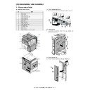
1. Operation panel section
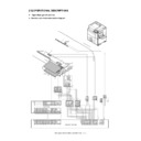
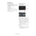
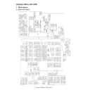
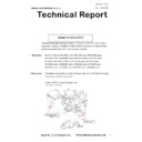
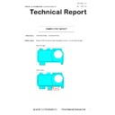
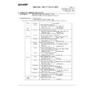
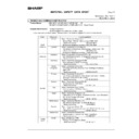
A. Electrical and mechanism relation diagram
2
3
1
6
5
4
4
1
2
3
4
5
6
7
8
9
10
11
12
13
14
15
16
17
18
19
20
21
22
23
24
25
26
27
28
29
30
31
32
33
34
35
36
37
38
39
40
41
FX16S-41S-0.5SV
CN-9
GND
nLCD_DISP
CN_LCDSEL1
CN_LCDSEL0
GND
GND
GND
GND
GND
GND
LCD_A3_P
LCD_A3_N
LCD_CLK_P
LCD_CLK_N
LCD_A2_P
LCD_A2_N
LCD_A1_P
LCD_A1_N
LCD_A0_P
LCD_A0_N
GND
GND
GND
GND
GND
GND
GND
GND
CN_nCCFT
+5VNSPSW
+5VNSPSW
+5VNSPSW
+5VNSPSW
+24V_PSW
+24V_PSW
+24V_PSW
+24V_PSW
3R3V_HUB_PSW
3R3V_HUB_PSW
OPE_TP_SCL
OPE_TP_SD
A
PHR-6
SRA-21T
-4
1
3
2
/SIZE_LED2
/SIZE_LED1
B3B-EH
EHR-3
5V
/OCSW
GND
24V
GND
2
3
4
5
6
1
/SIZE_LED1
/SIZE_LED2
CN-5
B6B-PH-K-S
5VC1
GND
/OCSW
24V
SCN MOTHER PWB
1
3
5
7
9
11
13
15
17
19
21
23
25
2
4
8
10
12
14
16
18
20
22
24
26
B26B-PNDZS
PNDP-26V
-Z
(1/2)CN-3
CN_OPELED_SEG0
CN_PDSEL1
INFO_LED_R
CN_PDSEL2
CN_PDSEL0
CN_nOPELED_FO
CN_nHOME_KEY
nINFO_F
AX_LED
INFO_LED_G
nPO
W_LED_G
+5V
O
nXL(X2)
+5V
GND
CN_PD
nWU_KEY
nPWR_SW
+5V
O
CN_BZR
YH(Y2)
GND
GND
nYL(Y1)
XH(X1)
nWU_LED
B6P-PH-K-S
PHR-6
6
1
2
3
4
5
PDSEL0
PDSEL1
PDSEL2
5V
PD
GND
1
3
2
B03B-P
ASK-1
CN1
P
AP-03V
-S
(NC)
nINFO_LED
5V
O
(NC)
6
6
GND
XAP-11V
-1
XARR-11V
11
11
12
V
10
10
XH(X1)
9
9
nYL(Y1)
8
8
YH(Y2)
7
7
nXL(X2)
5
5
+5V
O
4
4
CN_BZR
3
3
CN_OPELED_SEG0
2
2
CN_nOPELED_FO
1
1
CN_nHOME_KEY
BM11B-GHS-TBT
CN-1
1
2
3
4
5
6
7
8
9
10
11
GHR-11V
-S
nHM_LED(/FO)
GND(PO
W_LED)
GND
/BZR
nHM_KEY
SEG0
nWU_KEY
WU_LED
5V
O
PO
W_LED
nPWRSW
BM08B-GHS-TBT
CN-1
GHR-08V
-S
TP-IF PWB
3
XH(X1)
/Y
L(Y1)
/XL(X2)
YH(Y2)
1
2
4
CN-2
52271-0469
8
YH(Y2)
7
/XL(X2)
6
/YL(Y1)
5
XH(X1)
3
INFO_L_G
4
INFO_L_R
1
GND
2
12V
4
4
SMP-07V
-NC
nPWR_SW
7
7
GND
2
2
nWU_LED
3
3
5
5
INFO_LED_G
1
1
nWU_KEY
6
6
INFO_LED_R
LVDS PWB
FI-RE-41CL
FX16S-41S-0.5SV
41
0
39
38
37
36
35
34
33
32
31
30
29
28
27
26
25
24
23
22
21
20
19
18
17
16
15
14
13
12
11
10
9
8
7
6
5
4
3
2
1
GND
n
L
CD_DISP
CN_LCDSEL1
CN_LCDSEL0
GND
GND
GND
GND
GND
GND
LCD_A3_P
LCD_A3_N
LCD_CLK_P
LCD_CLK_N
LCD_A2_P
LCD_A2_N
LCD_A1_P
LCD_A1_N
LCD_A0_P
LCD_A0_N
GND
GND
GND
GND
GND
GND
GND
GND
CN_nCCFT
YH(Y2)
nHL(X2)
nYL(Y1)
XH(X1)
+5VNSPSW
+5VNSPSW
+5VNSPSW
+5VNSPSW
+24V_PSW
+24V_PSW
+24V_PSW
+24V_PSW
CN-3
28
27
26
25
24
23
22
21
20
19
18
17
16
15
14
13
12
11
10
9
8
7
6
5
4
3
2
1
CN-4
FI-RE41S-VF
GND
G
ND
GND
GND
GND
GND
GND
GND
GND
GND
3.3V
3.3V
DDC3.3V
CLKEDID
D
A
T
AEDID
TXOUT0-
TXOUT0+
TXOUT1-
TXOUT1+
TXOUT2-
TXOUT2+
TCLK-
TCLK+
CCFT
out
DISP
out
18V_LCD
18V_LCD
18V_LCD
FI-RE-41CL
PO
W_LED_G
SMR-O7V
-N
PWRSW
WU_KEY
WU_KEY
CCFT
OCSW
ORS-PD
MX-7040N OPERATIONAL DESCRIPTIONS 13 – 2
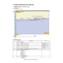
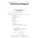
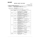
B. Operational descriptions
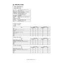
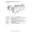
The operation panel unit is composed of the LCD unit, the LVDS PWB, the USB I/F PWB, and the KEY PWB. It displays the machine operation.
It is provided with the USB I/F which is used for the firmware update, USB print, and Scan to USB.
It is provided with the USB I/F which is used for the firmware update, USB print, and Scan to USB.
In addition, the USB I/F line is provided inside the operation panel to connect with the keyboard and the IC card reader.
A document size is detected by the document size detection PWB (light emitting) and the document size detection PWB (light receiving).
The detection timing of document size is determined according to the document size detection trigger sensor signal.
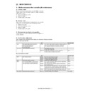
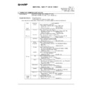
Signal name
Name
Function/Operation
HM_KEY
Home Screen key
Switch for home screen
OCSW
Document size detection trigger sensor
Generates the document size detection trigger signal.
PWRSW
Operation panel power switch
Turns ON/OFF the power on the secondary side.
WU_KEY
Power Save key
Switch for power save
No.
Name
Function/Operation
1
LVDS PWB
Converts the display data signal to the LCD display signal. / Controls the touch panel.
2
Document size detection PWB (Light emitting)
Drives the LED for the document size detection.
3
Document size detection PWB (Light receiving)
Outputs the document size detection signal.
4
USB I/F PWB
USB Interface
5
KEY PWB
Outputs the key operation signal.
6
Power lamp PWB
Power lamp display
7
Touch panel
Touch panel
8
LCD
LCD
MX-7040N OPERATIONAL DESCRIPTIONS 13 – 3
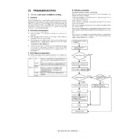
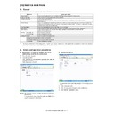
2. DSPF section
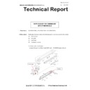
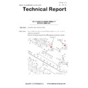
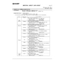
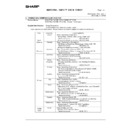
A. Electrical and mechanical relation diagram
(1)
Paper feed section
P
HNR-03-H
P
HNR-03-H+B
U03P-TR-P-H
10
9
3
P
HNR-03-H+B
U03P-TR-P-H
12
13
17
CN7
SGND
5V
2
1
2
4
11
P
HNR-03-H
1
SGND
18
14
15
16
B
1
8B-PHDSS-B
D_SOCV
5V(sensor)
D_SPED1
5
6
7
8
1
2
SGND
SGND
SGND
5V(sensor)
5V(sensor)
D_STUD
7
8
9
10
B10B-PHDSS-B
SGND
5V
D_SPPD1
B9B-PH-K-S
D_SPLS2
SGND
1
2
3
4
5
6
D_SLUM/A
2
D_SLUMB
3
D_SLUMA
4
D_SPLS1
5V(sensor)
V
AREF
5V(sensor)
5V(sensor)
CN2
3
4
D_SPED2
D_SPWS
A
GND
SGND
SGND
8
SGND
CN
4
NC(SGND)
2
5V(sensor)
5V(sensor)
9
5
4
5
6
D_SPUMB
D_SPUM/B
CN6
B
6B-PH-K-S
D_SPUM/A
D_SPUMA
24V_SPUM
24V_SPUM
1
2
3
D_SPLS1
D_SPLS2
5V(sensor)
1
2
3
SGND
D_RANDOM
24V_TR
/D_SPFC
SGND
D_STLD
1
175487-3
SGND
1
2
5V(sensor)
3
175487-3
V
AREF
D_SPWS
A
GND
V
AREF
D_SPWS
A
GND
1
2
3
3
2
1
24V_TR
5
D_SLUM/B
1
D_SPOD
6
7
D_STLD
SGND
5V(sensor)
175487-3
PHR-3
24V_TR
/D_SPFC
1
SGND
2
3
5V(sensor)
D_SPED2
SGND
5V(sensor)
D_SPPD1
5V(sensor)
B
5B-PH-K-S
1
2
1
2
3
3
PHR-3
1
SGND
DRIVER PWB
175487-3
175487-3
1
175487-3
1
SGND
175487-3
D_SOCV
D_SPED1
1
2
SGND
3
2
SGND
3
5V(sensor)
D_STUD
2
3
5V
D_RANDOM
2
3
5V
21
22
23
24
25
26
B
2
6
B-PHDSS-B
P
GND
20
21
22
23
16
17
18
19
12
13
14
15
5
6
7
8
9
10
11
24
25
26
12
13
14
15
16
17
18
19
4
5
6
7
8
9
10
D_
SPO
M_
DIR
11
1
2
3
CN2
DSPF CNT PWB
B
2
6
B-PHDSS-B
20
24V
P
GND
24V
P
GND
24V
P
GND
D_
SPU
M_IN/B
D_SLUMA
D_
SPO
M_ENA
D_
SPO
M_
STEP
D_
SPO
M_
MODE
D_SULM/A
D_SLUMB
D_SLUM/B
D_SPOD
D_
SPU
M_INA
D_
SPU
M_IN/A
D_
SPU
M_INB
D_
SPU
M_INA
SGND
D_SPPD1
D_
SPU
M_IN/A
D_SOCV
D_SPOD
D_
SPU
M_INB
D_
SPU
M_IN/B
D_SLUMA
D_SULM/A
D_SLUMB
D_SLUM/B
D_
SPO
M_ENA
D_
SPO
M_
STEP
D_
SPO
M_
MODE
P
GND
24V
D_SPO
M_
DIR
24V
P
GND
24V
5V
SGND
D_SPFF
AN
SGND
D_SPPD1
D_RANDOM
D_SOCV
D_RANDOM
1
2
3
4
CN8
SGND
D_SPFF
AN
5V
CN1
7
2
3
4
5
6
1
19
18
17
16
15
14
13
12
11
10
9
8
20
26
25
24
23
22
21
27
28
CN-3
B28B-PHDSS-B
D_SPUM_VREF
D_SPFM_VREF
D_SPOM_VREF1
D_SPOM_VREF2
D_SELA
D_SELB
D_SELC
D_SELOUT
3.3V
D_SPWS
A
GND
D_SPFC
D_SRRC
D_SRRBC
D_SPFM_M1
D_SPFM_M2
D_SPFM_CLK
D_SPFM_DIREC
D_STRRC
D_STRRBC
D_STMPS
/D_STRC
5V
SGND
5VPWM
SPED
5V0
SGND
(NC)
(NC)
7
2
3
4
5
6
1
19
18
17
16
15
14
13
12
11
10
9
8
20
26
25
24
23
22
21
25
28
D_SPUM_VREF
D_SPFM_VREF
D_SPOM_VREF1
D_SPOM_VREF2
D_SELA
D_SELB
D_SELC
D_SELOUT
3.3V
D_SPWS
A
GND
D_SPFC
D_SRRC
D_SRRBC
D_SPFM_M1
D_SPFM_M2
D_SPFM_CLK
D_SPFM_DIREC
D_STRRC
D_STRRBC
D_STMPS
/D_STRC
SGND
5VPWM
SPED
5V0
SGND
5V
27
(NC)
(NC)
B28B-PHDSS-B
CN-3
SPUM
SLUM
SPED2
STUD
SPED1
SPFC
SCOV
SPPD1
SPRDMD
SPLS1
SPWS
SPLS2
STLD
MX-7040N OPERATIONAL DESCRIPTIONS 13 – 4
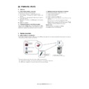
(2)
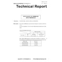
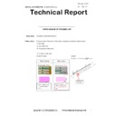
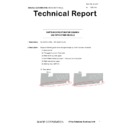
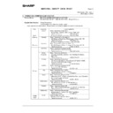
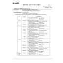
Upper transport section
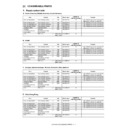
Signal name
Name
Function/Operation
SCOV
DSPF upper door open/close sensor
Detects open/close of the upper door.
SLUM
DSPF lift-up motor
Lifts up or moves down the document feed tray.
SPED1
DSPF document upper limit sensor
Detects the upper limit of the DSPF document.
SPED2
DSPF document empty sensor
Detects document empty in the document feed tray.
SPFC
DSPF document feed clutch
Controls ON/OFF of the rollers in the document feed section.
SPLS1
DSPF document length detection short sensor
Detects the document length of the document feed tray upper.
SPLS2
DSPF document length detection long sensor
Detects the document length of the document feed tray upper.
SPPD1
DSPF document pass sensor 1
Detects pass of the document.
SPRDMD
DSPF document random sensor
Detects the document size in random document feed.
SPUM
DSPF document feed motor
Drives the rollers and transport rollers in the document feed section.
SPWS
DSPF document width sensor
Detects the document width of the document feed tray upper.
STLD
DSPF document feed tray lower limit sensor
Detects the lower limit of the document feed tray.
STUD
DSPF document feed tray upper limit sensor
Detects the upper limit of the document feed tray.
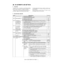
No.
Name
Function/ Operation
1
Pickup roller
Picks up a document and feeds it to the document feed roller.
2
Document feed roller
Performs the document feed operation of documents.
3
Separation roller
Separate a document to prevent against double-feed.
4
Torque limiter
A fixed level of resistance is always provided for rotation of the separation roller to prevent double feed.
Signal name
Name
Function/Operation
SPPD2
DSPF document pass sensor 2
Detects pass of the document.
SPUM
DSPF document feed motor
Drives the rollers, transport rollers and transport rollers in the document feed section.
STRC
DSPF transport roller clutch
Controls ON/OFF of the transport roller 1.
STRRC
DSPF No.1 registration roller clutch
Controls ON/OFF of No. 1 registration roller.
No.
Name
Function/ Operation
1
No. 1 registration roller (Drive)
Performs registration of document transport.
2
Transport roller 1 (Drive)
Transports document from No. 1 registration roller to No. 2 registration roller.
D_SPPD2
1
SGND
2
3
3
5V
B3B-PH-K-S
24V_TR
D_SPFM
B
D_SPF
M/B
/D_STMP
24V_TR
/D_STRRBC
24V_TR
/D_STRRC
/D_STRRC
1
SGND
D_STSET
24V_TR
PGND
F
AN_LOCK
NC(
F
A
N_PWM)
/D_SRRC
24V_TR
D_SPF
M/A
D_SPF
MA
24V_SPF
M
6
7
8
/D_SRRBC
24V_TR
CN9
24V_SPF
M
3
4
5
2
13
14
15
16
9
10
11
12
19
20
NC
24V_TR
NC
NC
/D_STRC
23
24
17
18
25
26
27
28
NC
21
22
B
2
8
B-PHDSS-B
/D_STRC
2
1
24V_TR
1
SMR-0
2V
-N
SMP-0
2
V
-NC
2
4
5
6
D_SPUMB
D_SPUM/B
B6B-PH-K-S
D_SPUM/A
D_SPUMA
24V_SPUM
24V_SPUM
1
2
3
2
1
24V_TR
1
2
6
10
12
4
D_SOCD
GND
5V
5V
5V
5V(sensor)
D_SPPD4
D_SPPD5
GND
D_SPPD2
D_SPPD3
GND
5V
GND
D_ROCD
5
7
9
11
17
5V(sensor)
GND
GND
14
16
18
15
1
2
3
8
CN1
B18B-PHDSS-B
13
DRIVER PWB
21
22
23
24
25
26
B
2
6
B-PHDSS-B
P
GND
20
21
22
23
16
17
18
19
12
13
14
15
5
6
7
8
9
10
11
24
25
26
12
13
14
15
16
17
18
19
4
5
6
7
8
9
10
D_
SPO
M_
DIR
11
1
2
3
CN2
DSPF CNT PWB
B
2
6
B-PHDSS-B
20
24V
P
GND
24V
P
GND
24V
P
GND
D_
SPU
M_IN/B
D_SLUMA
D_
SPO
M_ENA
D_
SPO
M_
STEP
D_
SPO
M_
MODE
D_SULM/A
D_SLUMB
D_SLUM/B
D_SPOD
D_
SPU
M_INA
D_
SPU
M_IN/A
D_
SPU
M_INB
D_
SPU
M_INA
SGND
D_SPPD1
D_
SPU
M_IN/A
D_SOCV
D_SPOD
D_
SPU
M_INB
D_
SPU
M_IN/B
D_SLUMA
D_SULM/A
D_SLUMB
D_SLUM/B
D_
SPO
M_ENA
D_
SPO
M_
STEP
D_
SPO
M_
MODE
P
GND
24V
D_SPO
M_
DIR
24V
P
GND
24V
5V
SGND
D_SPFF
AN
SGND
D_SPPD1
D_RANDOM
D_SOCV
D_RANDOM
1
2
3
4
CN
8
SGND
D_SPFF
AN
5V
PHNR-02-H+B
U02P-TR-P-H
PHNR-02-H
CN7
7
2
3
4
5
6
1
19
18
17
16
15
14
13
12
11
10
9
8
20
26
25
24
23
22
21
27
28
CN-3
B28B-PHDSS-B
D_SPUM_VREF
D_SPFM_VREF
D_SPOM_VREF1
D_SPOM_VREF2
D_SELA
D_SELB
D_SELC
D_SELOUT
3.3V
D_SPWS
A
GND
D_SPFC
D_SRRC
D_SRRBC
D_SPFM_M1
D_SPFM_M2
D_SPFM_CLK
D_SPFM_DIREC
D_STRRC
D_STRRBC
D_STMPS
/D_STRC
5V
SGND
5VPWM
SPED
5V0
SGND
(NC)
(NC)
7
2
3
4
5
6
1
19
18
17
16
15
14
13
12
11
10
9
8
20
26
25
24
23
22
21
25
28
D_SPUM_VREF
D_SPFM_VREF
D_SPOM_VREF1
D_SPOM_VREF2
D_SELA
D_SELB
D_SELC
D_SELOUT
3.3V
D_SPWS
A
GND
D_SPFC
D_SRRC
D_SRRBC
D_SPFM_M1
D_SPFM_M2
D_SPFM_CLK
D_SPFM_DIREC
D_STRRC
D_STRRBC
D_STMPS
/D_STRC
SGND
5VPWM
SPED
5V0
SGND
5V
27
(NC)
(NC)
B28B-PHDSS-B
CN-3
SPUM
STRRC
STRC
SPPD2

