Sharp AR-651 (serv.man23) Service Manual ▷ View online
3.
Main Service Parts for Safety
• The breaker's, door switch's, fuse's, thermostat's, thermofuse's, thermistor's, etc. are particularly
important for safety. Be sure to handle/install them properly. Do not allow a short circuit to occur to
maintain the safety rating of the equipment replace these parts with only genuine Sharp parts of
the same type and makers.
4.
Cautionary Labels
• During servicing, be sure to check the rating plate and the cautionary labels such as “Unplug the
power cord during service”, “Hot area”, “Laser warning label” etc. to ensure they are legrable a
properly installed to the equipment.
5.
Disposition of Consumable Parts, Packing Materials, Used batteries and RAM-ICs
• Regarding the recovery and disposal of the copier, supplies, consumable parts, packing materials,
used batteries and RAM-ICs including litium batteries, it is recommended to follow the relevant
local regulations or rules.
6.
When parts are disassembled, reassembly is basically the reverse of disassembly unless
otherwise noted in this manual or other related documents. Be careful not to reassemble
small parts such as screws, washers, pins, E-rings, star washers in the wrong places or in the
wrong order.
7.
Basically, the machine should not be operated with any parts removed or disassembled.
8.
Precautions Against Static Electricity
• The PC board must be stored in an anti-electrostatic bag and handled carefully using a wristband,
because the ICs on it may become damaged due to static electricity.
Caution: Before using the wristband, pull out the power cord plug of the copier and make
sure that there are no uninsulated charged objects in the vicinity.
Caution :
Dispose of used batteries and RAM-ICs including lithium batteries
according with Federal, State and local regulations.
Attention :
Se débarrasser de batteries et RAM-ICs usés y compris les batteries en
lithium selon ce manuel.
Vorsicht :
Entsorgung des gebrauchten Batterien und RAM-ICs (inklusive
der Lithium-Batterie) nach diesem Handbuch.
I
CONTENTS
1.
SPECIFICATIONS
1. 1.
Specifications . . . . . . . . . . . . . . . . . . 1-1
1. 2.
Accessories . . . . . . . . . . . . . . . . . . . 1-13
1. 3.
Options . . . . . . . . . . . . . . . . . . . . . . 1-13
1. 4.
Supplies. . . . . . . . . . . . . . . . . . . . . . 1-14
1. 5.
System List . . . . . . . . . . . . . . . . . . . 1-15
2.
COMPONENT LAYOUT & FUNCTIONS
2. 1.
Sectional View. . . . . . . . . . . . . . . . . . 2-1
2. 2.
Electric Parts Layout . . . . . . . . . . . . . 2-5
2. 3.
Symbols and Functions of
Various Components. . . . . . . . . . . . 2-16
Various Components. . . . . . . . . . . . 2-16
2. 4.
Symbols and Functions of
RADF Various Components . . . . . . 2-24
RADF Various Components . . . . . . 2-24
2. 5.
System Block Layout. . . . . . . . . . . . 2-26
2. 6.
Disassembly and Replacement
of Covers and PC Boards . . . . . . . . 2-27
of Covers and PC Boards . . . . . . . . 2-27
3.
COPY PROCESS
3. 1.
General Description. . . . . . . . . . . . . . 3-1
3. 2.
Details of Copy Process . . . . . . . . . . 3-2
3. 3.
Comparison of Copy Process
to AR-650/800 . . . . . . . . . . . . . . . . . 3-10
to AR-650/800 . . . . . . . . . . . . . . . . . 3-10
4.
GENERAL OPERATIONS
4. 1.
Overview of Operation. . . . . . . . . . . . 4-1
4. 2.
Operation. . . . . . . . . . . . . . . . . . . . . . 4-1
4. 3.
Abnormality Detection . . . . . . . . . . . . 4-6
4. 4.
Flowchart. . . . . . . . . . . . . . . . . . . . . 4-11
5.
CONTROL PANEL
5. 1.
Control Panel and Display Panel. . . . 5-1
5. 2.
Items Shown on Display Panel . . . . . 5-2
5. 3.
Relation between Copier State
and Operator’s Action . . . . . . . . . . . . 5-7
and Operator’s Action . . . . . . . . . . . . 5-7
5. 4.
Operation. . . . . . . . . . . . . . . . . . . . . . 5-8
5. 5.
Disassembly and Replacement. . . . 5-11
6.
SCANNING SECTION
6. 1.
Function. . . . . . . . . . . . . . . . . . . . . . . 6-1
6. 2.
Construction . . . . . . . . . . . . . . . . . . . 6-2
6. 3.
Operation. . . . . . . . . . . . . . . . . . . . . . 6-4
6. 4.
Control for Exposure Lamp . . . . . . . . 6-7
6. 5.
CCD Control . . . . . . . . . . . . . . . . . . 6-10
6. 6.
Automatic Original Size
Detection Circuit . . . . . . . . . . . . . . . 6-11
Detection Circuit . . . . . . . . . . . . . . . 6-11
6. 7.
Disassembly and Replacement. . . . 6-15
7.
IMAGE PROCESSING
7. 1.
General Description . . . . . . . . . . . . . 7-1
7. 2.
Image Processing Circuit . . . . . . . . . 7-2
7. 3.
SLG Board (PWA-F-SLG-340) . . . . . 7-4
7. 4.
PLG Board (PWA-F-PLG-340) . . . . . 7-7
7. 5.
Scanning Section . . . . . . . . . . . . . . . 7-8
7. 6.
Writing Section . . . . . . . . . . . . . . . . . 7-8
8.
LASER & OPTICAL UNIT
8. 1.
General Description . . . . . . . . . . . . . 8-1
8. 2.
Structure . . . . . . . . . . . . . . . . . . . . . . 8-3
8. 3.
Laser Diode . . . . . . . . . . . . . . . . . . . 8-7
8. 4.
Disassembly and Replacement . . . . 8-8
9.
PAPER FEEDING SECTION
9. 1.
General Description . . . . . . . . . . . . . 9-1
9. 2.
Functions . . . . . . . . . . . . . . . . . . . . . 9-1
9. 3.
Operation . . . . . . . . . . . . . . . . . . . . . 9-4
9. 4.
Drive Circuit for Tray-up Motor . . . . 9-10
9. 5.
Disassembly and Replacement . . . 9-11
10. PROCESS SECTION
10. 1.
Construction . . . . . . . . . . . . . . . . . . 10-1
10. 2.
Functions . . . . . . . . . . . . . . . . . . . . 10-2
10. 3.
Charger Wire Cleaner
Operational Circuit . . . . . . . . . . . . . 10-3
Operational Circuit . . . . . . . . . . . . . 10-3
10. 4.
High-voltage Transformer
Output Control Circuit . . . . . . . . . . . 10-4
Output Control Circuit . . . . . . . . . . . 10-4
10. 5.
Surface Potential Sensor . . . . . . . . 10-6
10. 6.
Disassembly and Replacement . . . 10-8
11. DRUM/CLEANER UNIT
11. 1.
Construction . . . . . . . . . . . . . . . . . . 11-1
11. 2.
Functions . . . . . . . . . . . . . . . . . . . . 11-2
11. 3.
Drum Temperature Detection
Circuit . . . . . . . . . . . . . . . . . . . . . . . 11-2
Circuit . . . . . . . . . . . . . . . . . . . . . . . 11-2
11. 4.
Image Quality Control . . . . . . . . . . . 11-3
11. 5.
Disassembly and Replacement . . . 11-6
12. DEVELOPER UNIT
12. 1.
Construction . . . . . . . . . . . . . . . . . . 12-1
12. 2.
Functions . . . . . . . . . . . . . . . . . . . . 12-2
12. 3.
Developer Unit Drive. . . . . . . . . . . . 12-4
12. 4.
Motor Drive Circuit . . . . . . . . . . . . . 12-6
12. 5.
Auto-toner Sensor Circuit . . . . . . . . 12-9
12. 6.
Disassembly and Replacement . . 12-12
13. TRANSFER/TRANSPORT UNIT
13. 1.
General Description . . . . . . . . . . . . 13-1
13. 2.
Operation . . . . . . . . . . . . . . . . . . . . 13-1
13. 3.
Functions . . . . . . . . . . . . . . . . . . . . 13-2
13. 4.
Disassembly and Replacement . . . 13-4
II
14. FUSER UNIT
14. 1.
General Description. . . . . . . . . . . . . 14-1
14. 2.
Operation. . . . . . . . . . . . . . . . . . . . . 14-1
14. 3.
Functions. . . . . . . . . . . . . . . . . . . . . 14-2
14. 4.
Heater Control Circuit . . . . . . . . . . . 14-4
14. 5.
Fuser Motor Drive . . . . . . . . . . . . . 14-11
14. 6.
Disassembly and Replacement. . . 14-13
15. EXIT/REVERSING UNIT
15. 1.
General Description. . . . . . . . . . . . . 15-1
15. 2.
Operation. . . . . . . . . . . . . . . . . . . . . 15-1
15. 3.
Disassembly and Replacement. . . . 15-6
16. RADF (DOCUMENT FEEDER)
16. 1.
General Description. . . . . . . . . . . . . 16-1
16. 2.
Construction . . . . . . . . . . . . . . . . . . 16-2
16. 3.
Drive System . . . . . . . . . . . . . . . . . . 16-3
16. 4.
Signal Block Diagram . . . . . . . . . . . 16-6
16. 5.
Operations. . . . . . . . . . . . . . . . . . . . 16-7
16. 6.
Jams . . . . . . . . . . . . . . . . . . . . . . . 16-32
16. 7.
Errors. . . . . . . . . . . . . . . . . . . . . . . 16-37
16. 8.
Original Size Detection . . . . . . . . . 16-38
16. 9.
Flow Chart . . . . . . . . . . . . . . . . . . . 16-41
16. 10. Timing Chart . . . . . . . . . . . . . . . . . 16-57
16. 11. Circuits . . . . . . . . . . . . . . . . . . . . . 16-62
16. 12. Input/Output Signals . . . . . . . . . . . 16-68
16. 13. Disassembly and Replacement. . . 16-73
16. 11. Circuits . . . . . . . . . . . . . . . . . . . . . 16-62
16. 12. Input/Output Signals . . . . . . . . . . . 16-68
16. 13. Disassembly and Replacement. . . 16-73
17. POWER SUPPLY UNIT
17. 1.
Construction . . . . . . . . . . . . . . . . . . 17-1
17. 2.
Operation of DC Output Circuits . . . 17-1
17. 3.
Output Channel . . . . . . . . . . . . . . . . 17-2
17. 4.
Fuse . . . . . . . . . . . . . . . . . . . . . . . . 17-5
17. 5.
Configuration of Power Supply
Unit . . . . . . . . . . . . . . . . . . . . . . . . . 17-7
Unit . . . . . . . . . . . . . . . . . . . . . . . . . 17-7
17. 6.
Power Supply Sequence . . . . . . . . . 17-8
18. PRINTED WIRING BOARDS . . . . . . . . . . . 18-1
19. UNPACKING AND INSTALLATION . . . . . . 19-1
AR-651/810 SPECIFICATIONS 1 - 1
1. SPECIFICATIONS
1.1. Specifications
1.1.1. System
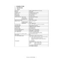
Copy system
Indirect electronic photo system (Dry type)
Body type
Console type
Original table type
Fixed type (Left rear reference)
Original cover
RADF standard provision
Frame structure
Fixed frame type
Photoconductor
OPC drum (
φ
100)
Original scan system
Scan sensor
CCD line sensor (7500 pixel)
Scan resolution
600 x 600 dpi
Scan light source
Xenon lamp
Scan data output system
1 scan multi copy system
Exposure system
Exposure light source
Semiconductor laser
Exposure resolution
600 dpi
Scan system
Use of Polygon mirror
Developing system
2-component magnetic brush development system
Discharging system
Photo discharge by red LED
Charging system
Negative corona system (Scorotron)
Transfer system
Transfer belt system
Separation system
Transfer belt system
Transfer belt cleaning system
Fur brush system + blade system
Drum cleaning system
Blade system + Fur brush system
Toner supply system
Front side toner cartridge supply
Note: Toner supply inhibited during printing
Toner concentration adjustment system
Magnetic auto toner system
Toner recycle
Yes
Toner empty detection system
Electric detection system (Auto toner sensor)
Note: When toner empty is detected, the toner supply symbol
flashes and the message is displayed.
Copying is inhibited until the toner concentration is
recovered.
Fusing system
Heat roller system
Induced heating
system
700 to 1450 W (100V)
6000 to 1500 W (115V)
700 to 1500 W (230V)
Roller diameter (Upper)
φ
60
Roller diameter (Lower)
φ
60

