Sharp AR-651 (serv.man7) Service Manual ▷ View online
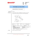
AR-651/810 COPY PROCESS 3 - 1
3. COPY PROCESS
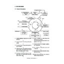
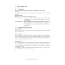
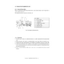
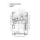
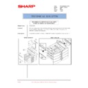
3. 1. General Description
(1) Charging: Negatively charges the surface of the
OPC drum.
훹
(2) Original exposure: Converts images into optical
signals.
훹
(3) Scanning: Converts image optical signals into
electrical signals.
훹
(4) Writing: Converts image electrical signals into
optical signals (laser emission) and exposes
them to the surface of the OPC drum.
훹
(5) Development: Makes the negatively-charged
toner adhere to the photoconductive drum and
forms a visible image.
훹
(6) Transfer: Transfers the visible image on the
OPC drum onto the paper.
Separation: Separates the paper from the drum
together with the toner.
훹
(7) Fusing: Fuses the toner on the paper by applying
heat and pressure.
훹
(8) Fur brush cleaning: Cleans dirt and paper dust
on the drum.
훹
(9) Blade cleaning: Forcibly removes the residual
toner on the drum.
훹
(10) Discharging: Discharges any remaining
negative charge on the drum.
2
3
1
9
4
5
8
7
–
–
–
–
–
–
–
–
–
–
–
–
–
–
–
– –
–
+
+
+
+
–
+
+
+
+
+ + + +
–
–
–
6
10
Image processing
Charging
-733V (grid voltage)
Original exposure
Xenon lamp
29W
Scanning
CCD
600dpi, 7500pixel
Writing
Semiconductor laser
Development
Magnetic roller
Bias -500VDC+AC
Pw=3.8nJ/mm
2
Bypass feeding
Cassette feeding
LCF feeding
Transfer/Separation
80µA
Cleaning brush + Blade
5µA
Fusing
Fuser roller
Discharging
Fur brush cleaning
Blade cleaning
Discharging
LED array (wavelength 660nm x 16)
Toner
Carrier
700~1450W
AR-651/810 COPY PROCESS 3 - 2
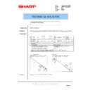
3. 2. Details of Copy Process
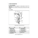
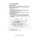
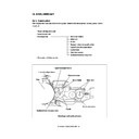
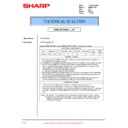
(1) OPC drum
The OPC drum has two layers, an outer and an inner
layer. The outer layer is a photovoltaic layer made of
an organic photovoltaic carrier (OPC). The inner layer
is an aluminum conductive base in a cylindrical form.
The photovoltaic carrier has the characteristic that
produces an electrical current depending on the
strength of the light exposed.
Example:
· Strong light
촞
A relatively large current is produced
· Weak light
촞
A relatively small current is produced
[Formation of electrostatic latent image]
In the processes of charging, scanning, printing and
discharging described below, negative potential on
the areas of the drum corresponding to black areas
of the original is eliminated, while the areas of the
drum corresponding to white areas remains the
negative charge.
As this image on the drum formed by the negative
potential is invisible, it is called an “electrostatic la-
tent image.”
Structure of the OPC drum
OPC layer
0
– 500
– 1000
Time (t)
Surface potential (V)
Black area of original
White area of original
Electric potential on the OPC drum
Dis-
charging
process
charging
process
Charging
process
process
Aluminum conductive base
OPC
AL core
Surface Charge
Prsipatron
Prsipatron
Resulting Hall
OPC Current Gen.
OPC Current Gen.
Laser
beam
beam
AR-651/810 COPY PROCESS 3 - 3
CCD light
receiving
amount
receiving
amount
Value of
image signals
to be output
image signals
to be output
Light
255
Dark
0
Difference between
"light " and "dark" is
divided into 256
steps.
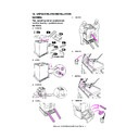
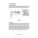
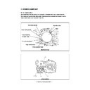
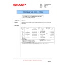
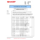
(3) Scanning
Scanning is a process of exposing the original to
the light and converting the reflection into electrical
signals.
The light reflected from the original is imported to
the charge coupled device (CCD) and this optical
image information is converted into electrical sig-
nals (image signals), which are then sent to the
image processing section.
CCD
Image processing
section
(Example)
쩪
쩪
Rotation of drum
Main charger
Grid control circuit
Discharge
transformer
(2) Charging
Charging is a process of applying a charge uniformly
to the photoconductive drum surface.
The charger wire produces a negative corona dis-
charge, which is controlled by the grid so that the
drum surface is uniformly charged with negative po-
tential.
The surface potential on the drum is determined by
the grid potential and controlled to a specifed value
by the grid control circuit as determined by the proc-
ess controll system.
AR-651/810 COPY PROCESS 3 - 4
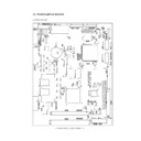
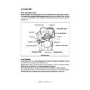
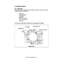
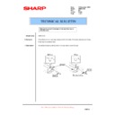
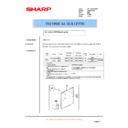
(5) Development
Development is a process of making the electro-
static latent images visible to the eye (visible im-
ages).
Developer material is supplied to the photoconduc-
tive drum surface by magnetic roller. The toner in
the developer material adheres to the areas on the
drum surface where the potential is lower than the
developer bias which is applied to the magnetic roller
(reverse development method).
OPC layer
Carrier (always attracted
onto the magnet)
onto the magnet)
Drum
Magnetic roller
Magnet
Magnetic roller
Toner
Toner
Bias voltage
–500 VDC
–500 VDC
OPC
drum
drum
Aluminum conductive
base
base
Toner
(4) Writing
Writing is a process of converting the image signals
sent from the image processing section into optical
signals and exposing the drum surface to the light.
Semiconductor laser elements convert image sig-
nals sent from the image processing section into
optical signals (laser emission) and exposes the
drum surface to the light to form an electrostatic
latent image on it.
Image
processing
section
Laser Drive
board
Semiconduc-
tor laser
element
Polygonal mirror
Photo-
conductive
drum
0
– 100V
– 200V
– 300V
– 400V
– 700V
– 500V
– 600V
Toner amount
applied to the
OPC drum’s
surface
applied to the
OPC drum’s
surface
White background
Half tone
Solid
White background
Image not developed
Bias
potential
potential
Image is developed by
toner
toner
The (–) potential
of the drum being
higher than the
developer bias
of the drum being
higher than the
developer bias
The (–) potential
of the drum being
lower than the
developer bias
of the drum being
lower than the
developer bias

