Sharp AR-651 (serv.man23) Service Manual ▷ View online
AR-651/810 PAPER FEEDING SECTION 9 - 7
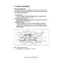
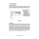
[E] Tandem LCF
(E-1) From power ON to standby status
(1) When the copier is turned ON, the power is supplied to start the pre-running operation. The tandem LCF
tray-up motor starts to rotate forward and raises the tray. The tandem LCF tray-up motor is turned OFF
when the tray turns ON the tandem LCF tray-up sensor, and the tray is then stopped. At this time, it is
judged whether there is paper on the feed side tray when the tandem LCF empty sensor is ON. On the
other hand, the absence of paper on the feed side tray is assumed when the sensor is OFF, and the
tandem LCF standby side empty sensor is subsequently checked. When the tandem LCF standby side
empty sensor is OFF, paper is absent on the standby side tray and it is therefore assumed that there
is no paper in the tandem LCF. When the tandem LCF standby side empty sensor is ON, paper on the
standby side tray is moved onto the feed side tray. The tandem LCF tray-up motor is rotated in reverse
and lowers the feed side tray. The lowered tray turns ON the tandem LCF tray bottom sensor, and the
tandem LCF tray-up motor is turned OFF to stop the tray. The end fence solenoid and pickup solenoid
are then turned ON. The end fence motor rotates forward and the paper on the standby side tray is
moved onto the feed side tray. The end fence motor is stopped for a second when the end fence stop
position sensor is turned ON, and the motor immediately starts to rotate in reverse to return the end
fence to the position where the end fence home position sensor is turned ON. When the returning
operation is started, the end fence solenoid and pickup solenoid are turned OFF, and the tandem LCF
tray-up motor is rotated forward to raise the tray. The tandem LCF tray-up motor is turned OFF when the
tray being raised turns ON the tandem LCF tray-up sensor and stops the tray. At this time, the pres-
ence of paper is judged when the tandem LCF empty sensor is ON.
(2) Whe the power is turned ON after the tray unit is removed, the tandem LCF tray-up motor is turned ON.
The tray is raised as soon as the tray unit detects that the tray is fully inserted.
(3) If either of the tandem LCF feed sensors is ON (there is paper at the transportation path) when turning
ON the power, a paper jam is judged and the operation is disabled until the paper is removed.
AR-651/810 PAPER FEEDING SECTION 9 - 8
(E-2) Standby status
(1) Trays detect the paper as described above, and the copier goes into the standby status.
(2) The tray goes down automatically when the tray unit is removed and is raised as soon as the tray unit
is reinstalled it then checks if there is paper in the tray.
(E-3) From the start to the end of copying
(1) The drum motor of the copier is turned ON when the [START] key is pressed. The transport motor is
also turned ON to drive the transfer belt unit.
(2) When the copier judges that the tandem LCF is ready for feeding paper, it turns ON the tandem LCF
feed clutch on the selected tray. This clutch drives the pickup roller and feed roller to feed paper from
the tray.
(3) In a specified time after the feeding has started, the appropriate transport clutch is turned ON to drive
the transport roller.
(4) The leading edge of the paper turns the feed sensor ON. These are located right next to the exit side of
the selected tray. The feed clutch is then turned OFF and feeding from the tray is complete.
(5) The paper is then transported to the copier by the transport rollers. If the trailing edge of the previous
sheet still remains at the transport sensor when the leading edge of the paper reaches the feed sensor,
the transport clutch is turned OFF to stop the transport of the paper at that time.
(6) The trailing edge of the paper turns the feed sensor OFF. These are located right next to the exit side of
the selected tray. The selected tray then becomes ready for feeding the next sheet of paper, and the
procedures (2) to (5) are repeated.
(7) When the copying operation is completed, the drum motor, the tandem LCF transport motor and transport
clutch are turned OFF and the transport roller is stopped.
(E-4) Error detection
a) Jam detection
(1) A paper jam occurs in the following cases.
a. Feed sensor is not turned ON within a specified time after the feeding has started.
b. The leading edge of the paper does not pass the feed sensor in the transport path within a fixed
time.
(2) Open the feed side lower cover and remove all the paper remaining on the transport path and close the
cover to clear the jammed paper. If either of the feed sensors is still ON when the cover is closed, it is
determined that there is still paper on the transport path and the paper jam status is not canceled.
(3) When a paper jam occurs in the paper feeder during multiple copying, the sheet that was fed before the
jam is copied normally.
AR-651/810 PAPER FEEDING SECTION 9 - 9
b) Call for service
(1) When the tandem LCF tray-up sensor is not turned ON even through a specified time has passed since
the tray started to be raised, it is assumed that the tray cannot be used (there is no paper) and the
corresponding message is displayed on the control panel.
(2) When the tandem LCF tray bottom sensor is not turned ON even through a specified time has passed
since the tray started to be lowered, it is assumed that the tray cannot be used (there is no paper) and
the corresponding message is displayed on the control panel.
(3) When the end fence stop position sensor is not turned ON even through a specified time has passed
since the end fence started to move the paper in the standby side tray, it is assumed that the tray
cannot be used (there is no paper) and the corresponding message is displayed on the control panel.
(4) When the end fence home position sensor is not turned ON even through a specified time has passed
since the end fence started to move the paper in the standby side, it is assumed that the tray cannot
be used (there is no paper) and the corresponding message is displayed on the control panel.
(5) The states (1) to (4) are cleared by removing the tray unit.
AR-651/810 PAPER FEEDING SECTION 9 - 10
9. 4. Drive Circuit for Tray-up Motor
Cassette tray-up motor (MOT)
: Driven by IC72 (tray-up motor 1) and IC36 (tray-up motor 2)
(LGC: TA8428)
Block diagram of TA8428
1
2
3
4
5
6
7
IN1
IN2
M(+)
GND
M(–)
N.C.
V
CC
IN1 and IN2 are input terminals to receive the signals from the microcomputer. The control logic, based on
the signals from the microcomputer, controls the rotation direction and ON/OFF of the motor.
Input
Output
IN1
IN2
M (+)
M (–)
Remarks
H
H
L
L
BRAKE
L
H
L
H
CW
H
L
H
L
CCW
L
L
OFF (high impedance) STOP
Control logic
Thermal shut-
down over-
current protec-
tion circuit
down over-
current protec-
tion circuit

