Sharp UP-800 (serv.man17) Service Manual ▷ View online
5-2
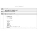
LT-1320CS
Repair power supply circuit
to provide rated voltage.
Ensure that connector is
correctly seated and gives
proper contact.
Replace thermal print head
unit.
Repair power supply circuit
to provide rated voltage.
Replace thermal print head
unit.
Clean head with soft cloth
moistened in ethanol (cleaning
alcohol).
Replace thermal print head
unit.
Repair power supply circuit
to provide rated voltage.
Clean head with soft cloth
moistened in ethanol (cleaning
alcohol).
Replace printer paper with
paper that meets specifi-
cations.
■ Servicing Procedure
When a problem has occurred, check the symptoms carefully and proceed according to the instructions given in the
section "Symptoms and Countermeasures".
● Symptom................. Look in this column for a condition that matches or closely resembles the current
● Symptom................. Look in this column for a condition that matches or closely resembles the current
condition of the printer. This will allow you to determine also hidden faults.
● Cause ...................... Possible causes are described in this column. To determine which cause applies in each
instance, use the check procedure described in the next column.
● Check ...................... Lists steps designed to pinpoint the cause of a problem.
● Countermeasure ...... This column lists the steps to be taken in order to correct the problem.
● Countermeasure ...... This column lists the steps to be taken in order to correct the problem.
Following the procedure outlined below will contribute to accurate diagnosis and ensure efficient troubleshooting.
■ Symptoms and Countermeasures
Symptom
Cause
Check
Countermeasure
Head is not powered correctly.
Thermal print head connector
faulty.
T h e r m a l p r i n t h e a d u n i t
defective.
Head is not powered correctly.
Thermal print head unit de-
fective.
Contamination or foreign
object on thermal print head.
T h e r m a l p r i n t h e a d u n i t
defective.
Head is not powered correctly.
Contamination or foreign
object on thermal print head.
Incorrect printer paper is used.
Use tester or oscilloscope to
measure power supply voltage.
Check connector contact con-
dition.
-
Use tester or oscilloscope to
measure power supply voltage.
-
Check thermal print head for
contamination.
-
Use tester or oscilloscope to
measure power supply voltage.
Check thermal print head for
contamination.
Check whether printer paper
meets specifications.
Unit does not print.
Print is faint.
Missing dots.
Print is dirty.
Print quality is bad.
Printing
problem
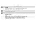
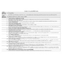
5-3
LT-1320CS
Symptom
Cause
Check
Countermeasure
Check connector contact con-
dition.
Use tester or oscilloscope to
measure power supply voltage.
Use tester or oscilloscope to
check lead wires in motor
assembly for continuity.
Use tester or oscilloscope to
measure power supply voltage.
Check the paper path for jam-
med or broken paper.
Remove gear cover and inspect
gear train.
Remove gear cover and inspect
gear train.
Use tester or oscilloscope to
measure power supply voltage.
Check connector contact con-
dition.
-
Check connector contact con-
dition.
-
Ensure that connector is
correctly seated and gives
proper contact.
Repair power supply circuit
to provide rated voltage.
Replace printer unit.
Replace printer unit.
Remove obstacles and set
the paper up correctly.
Remove any foreign object.
Replace printer unit.
Replace printer unit.
Ensure that connector is
correctly seated and gives
proper contact.
Replace printer unit.
Ensure that connector is
correctly seated and gives
proper contact.
Replace printer unit.
Paper feed motor
does not operate
or operates erra-
tically.
Paper is not being
transported
Paper absence or
presence is not
detected correctly.
Head down con-
dition is not de-
tected.
Motor connector faulty.
Motor is not powered correctly.
Lead wire inside motor assembly
is broken.
Motor is defective.
Problem in paper feed path.
Gear jammed by foreign object.
Gear is broken.
Motor is defective.
Sensor connector faulty.
Paper sensor is defective.
Sensor connector faulty.
Head up sensor is defective.
Paper
feed
problem
Sensor
problem

