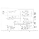
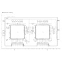
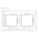
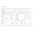
Sharp LC-45GD1E (serv.man29) Service Manual ▷ View online
64
TU-45GD1E
LC-45GD1E
LC-45GD1E
TROUBLE SHOOTING TABLE
(Continued)
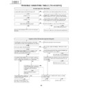
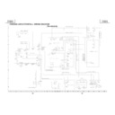
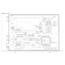
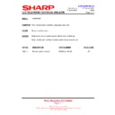
The screen is partially whitish or dark.
YES
YES
NO
NO
Is the gradation pattern displayed normally
when setting PATTERN1 of PATTERN
PAGE1 in the adjustment process menu to
02? (Is it whitish or dark?)
when setting PATTERN1 of PATTERN
PAGE1 in the adjustment process menu to
02? (Is it whitish or dark?)
When checking the picture
by connecting the AVC
center, the whole screen is
whitish or dark.
by connecting the AVC
center, the whole screen is
whitish or dark.
Remove the FPC connected to
SC4701, SC4702, SC6801 and
SC6802 (to prevent the panel from
being damaged).
SC4701, SC4702, SC6801 and
SC6802 (to prevent the panel from
being damaged).
Check the AVC.
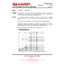
Check the voltages supplied to the
panel:
Pin (2): VH0 7.47V
Pin (3): VH31 9.48V
Pin (4): VH63 9.74V
Pin (5): VH95 10.11V
Pin (6): VH127 10.47V
Pin (7): VH159 10.93V
Pin (8): VH191 11.41V
Pin (9): VH247 12.30V
Pin (10): VH255 14.2V
Pin (11): VLS 15V
Pin (30): VSH 3.3V
Pin (64): VL0 7.42V
Pin (63): VL31 5.32V
Pin (62): VL63 4.93V
Pin (61): VL95 4.53V
Pin (60): VL127 4.06V
Pin (59): VL159 3.55V
Pin (58): VL191 3.06V
Pin (57): VL247 0.99V
Pin (56): VL255 0.28V
Pin (76): VGH Square wave (32V-15V)
Pin (78): VGL -7V
65
TU-45GD1E
LC-45GD1E
LC-45GD1E
TROUBLE SHOOTING TABLE
(Continued)
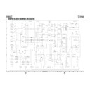
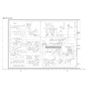
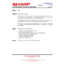
Card troubleshooting
Are the software version of the PC card first
and then the V
ersion No?
Is that the newest V
ersion No.?
When the panel is changed to the Card
Window
, does the panel flash?
YES
YES
YES
YES
YES
YES
YES
YES
YES
YES
Does Pin (32) of IC5101 show 3.3V?
Is voltage at Pins (28)(27) of SC5102 within
1.25±0.2V?
Is the socket of SC5102 inserted correctly?
Is the H.V output to Pins (6)(7) of IC5101?
Is the CLK output to Pin (31) of IC5101?
The problem probably results from the factor
other than the card PWB.
Upgrade the version of the soft.
See page 28
Confirm that solder at
R5141/R5142/R5144/R5134 is not wet.
Reinsert the socket.
Solder of SC5102/IC5101 may bridge.
Check SC5102/IC5102 and peripheral
circuits.
IC5001/IC5003/IC5006 may be defective.
Still loading
Thumb-nails or index are displayed.
Is the PC card applicable?
W
ait for about 5 minutes from inserting the
card in the state of loading.
NO
NO
NO
NO
NO
NO
NO
NO
Even with the card is inserted, freeze
occurs in the state of loading.
The card may be unapplicable/unconfirmed
or defect.
T
ry other cards to check if the same
problem occurs.
Also check that the card is
readable by PC.
NO
NO
In the following cases, it may take long time
to access.
These cases are not defect.
•A
lot of files
•A
lot of folders
•Card having large capacity
•Card accessing at slow rate (early CF
, SM,
MS or etc.)
•In the case of that adapters are used in
double or triple
SD
-->CF type SD adapter
--> PCMCIA
adapter
mini SD
--> mini SD adapter
--> PCMCIA
adapter etc.
•Card having some large files
1
2
See to operation
manual or the Sharp
We
b-site.
NO
NO
NO
NO
Output from Pin (3) of IC5605 is
3.3V or 5V
Does Pin (1) of P5003 show 10V?
IC5103 and peripheral circuits may
be defective, or Q5103 may be
damaged.
YES
Output from Pin (2) of IC5605 is
not lower than 2V
.
YES
YES
YES
Input to Pin (1) of IC5605 is not
lower than 4V
.
IC5001 may be defective.
IC5001 may be defective.
The
A
V
PWB or SUB POWER PWB
may have problems.
Make sure that about
2.7V is even NG.
NO
The buf
fer circuit of IC5601 thru
5607 and IC5001 may be
defective.
Or the PC card may be defective.
T
ry other cards to check if the
same problem occurs.
Also check the card is readable by
PC.
YES
Defective contact, bending of pins
or that solder is not wet may be
occurring.
Repair the corresponding places.
Reinsert the
SC5602 card
slot to confirm.
66
TU-45GD1E
LC-45GD1E
LC-45GD1E
TROUBLE SHOOTING TABLE
(Continued)
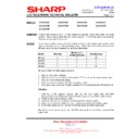
Is the power 3.3V input to Pin (3) of P5003?
Is the socket of SC5102 inserted?
YES
YES
YES
YES
YES
OK
Is the power 1.5V output to Pin (3) of
IC5004?
Is voltage of R5101/5102 3.3V?
Is voltage of Pin (3) of S5001 (RESET
SW)3.3V?
Check that solder of the IC5003 (32MB
flash memory) is not wet.
Replace the IC5003 (flash memory) or re-
upgrade version of the soft.
Check which is the cause, the PC PWB or
Main PWB.
(Disconnect SC5102/P5003 and check
impedance of Gnd-3.3V is about 8.9k
Ω
)
Reinsert the socket.
The power Reg IC5004 may be damaged
or IC5001/5201 may be defective.
(Impedance of Gnd-1.5V is about 700
Ω
)
The solder bridge at SC5102 or defect of
IC5001 may be occurring.
(Impedance of Gnd-1.5V is about 19.5k
Ω
)
R5102 is defective.
Repair the corresponding places.
NO
NO
NO
NO
NO
NG
1
Especially
,
check that Pins
(1)(24)(25)(48)
is not wet.
See Page 28
NO
NO
Change R2593/2594/2595/2596 in
the
A
V
PWB from 100
Ω
into 47
Ω
.
Recorded movies have spluttering
noise.
Movies are played at slow rate.
YES
YES
Check the connector of P5003.
Check that the clock of I2S line is
installed in
A
V
-PWB-PC Card.
On switching inputs, add R5041
10k
Ω
to take measures for noise.
2
A
CI card is not recognized.
Are Pins in SC9101 folded or crooked?
Is 27MHz CLK input to Pin (35) of IC9101?
Check X9101 and peripheral circuits.
Replace SC9101.
NO
Are Pins (17), (18), (51) and (52) of SC9101
supplied with 5V voltage?
NO
NO
NO
Check IC9102, IC9014, IC9001 and
peripheral circuits.
Is 3.3V voltage applied on the power Pin of
each of IC9101, IC9103, IC9104 and
IC9105?
Check IC9101, IC9103, IC9104, IC9105 and
peripheral circuits (data, address).
Check IC9002 and peripheral circuits.
YES
YES
YES
YES
(DVB-UNIT)
67
TU-45GD1E
LC-45GD1E
LC-45GD1E
- M E M O -

