Sharp LC-45GD1E (serv.man26) Service Manual ▷ View online
17
TU-45GD1E
LC-45GD1E
LC-45GD1E
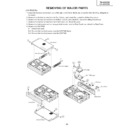
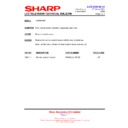
REMOVING OF MAJOR PARTS
(TU-45GD1E)
1.Remove the two lock screws from each of the right and left Side Shield, and detach the Side Shield by sliding them
backward.
2. Remove the five lock screws from the Top Cabinet, and detach the cabinet by sliding it backward.
3. Remove the five lock screws from the Bottom Cabinet, and detach the cabinet by sliding it backward.
4. Remove the tow lock screws from the Front Panel, and detach the panel.
5. Remove the lock screws and six hexagon shaft screws from the Rear Panel, and detach the Rear Panel.
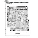
6. Remove the DVI PWB.
6-1. Remove the revit.
6-2. Remove the four lock screws from the DVI PWB Angle.
6-3. Remove the four lock screws from the DVI PWB.
6-2. Remove the four lock screws from the DVI PWB Angle.
6-3. Remove the four lock screws from the DVI PWB.
1
1
2
2
2
Top Cabinet
Side Shield (Right)
Side Shield (Left)
3
3
3
4
Bottom Cabinet
Front Panel
5
5
5
6-2
6-3
6-1
Rear Panel
DVI PWB
DVI PWB Angle
SD Cover
Card Cover
18
TU-45GD1E
LC-45GD1E
LC-45GD1E
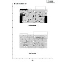
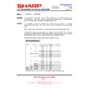
7. Remove the DC/DC Converter PWB, TMDS PWB and AUDIO I/F PWB.
7-1. Remove the four lock screws from the TMDS PWB angle.
7-2. Remove the four lock screws from the DC/DC Converter PWB.
7-3. Remove the four lock screws from the TMDS PWB.
7-4. Remove the two lock screws from the AUDIO I/F PWB.
7-2. Remove the four lock screws from the DC/DC Converter PWB.
7-3. Remove the four lock screws from the TMDS PWB.
7-4. Remove the two lock screws from the AUDIO I/F PWB.
8. Remove the five lock screws from the Power PWB.
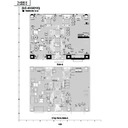
9. Remove the AV PWB, PC Card PWB and 1-bit AMP PWB.
9. Remove the AV PWB, PC Card PWB and 1-bit AMP PWB.
9-1. Remove the five lock screws from the AV PWB.
9-2. Remove the two lock screws from the 1-bit AMP PWB.
9-3. Remove the three lock screws from PC Card PWB.
9-4. Remove the six lock screws from AV PWB Angle.
9-2. Remove the two lock screws from the 1-bit AMP PWB.
9-3. Remove the three lock screws from PC Card PWB.
9-4. Remove the six lock screws from AV PWB Angle.
7-2
7-1
7-1
7-3
7-4
DC/DC
Converter
PWB
Converter
PWB
TMDS PWB Shield
TMDS PWB
TMDS PWB Angle
AUDIO I/F PWB
8
Power PWB
9-1
9-2
9-3
9-4
AV PWB
PC Card PWB
1-bit Amplifier PWB
AV PWB Angle
19
TU-45GD1E
LC-45GD1E
LC-45GD1E
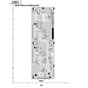
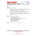
10. Remove the cooling fan (large), MAIN PWB and CPU PWB.
10-1. Detach the Cooling Fan (large).
10-2. Remove the seven lock screws from the Main PWB.
10-3. Remove the six lock screws from the DVB-T PWB.
10-4. Remove the five lock screws from the CPU PWB.
10-2. Remove the seven lock screws from the Main PWB.
10-3. Remove the six lock screws from the DVB-T PWB.
10-4. Remove the five lock screws from the CPU PWB.
11. Remove the Cooling Fan (small) and Front PWB.
11-1. Detach the Cooling Fan (small).
11-2. Remove the four lock screws from the Front Shield.
11-3. Remove the one lock screw from the Front PWB.
11-2. Remove the four lock screws from the Front Shield.
11-3. Remove the one lock screw from the Front PWB.
11-2
11-3
11-1
Front Shield
Front PWB
Cooling Fan
10-2
10-4
10-3
10-1
Main PWB Angle
Cooling Fan
DVB-T PWB
CPU PWB
DVB-T Shield
Main PWB
Radiating
Shield
Ass’y
Shield
Ass’y
CPU Shield
20
TU-45GD1E
LC-45GD1E
LC-45GD1E
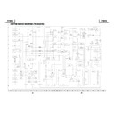
(LC-45GD1E)
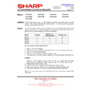
1. Remove the Terminal Covers 1 .
2. Remove the four lock screws 2 and detach the Stand.
3. Remove the four lock screws 3 and detach the Bracket Covers.
4. Remove the four lock screws 4 and separate the Speaker Box from the set.
Disconnect SP wire (R) and SP wire (L).
5. Remove the twenty one lock screws 5 from Rear Cabinet, and detach the Rear Cabinet.
6. Remove the eight lock screws 6 from Center Angle, and detach the Center Angle.
7. Remove the KEY PWB
7-1. Remove the two lock screws 7 from Top Control Cover.
7-2. Remove the three lock screws 8 from the KEY PWB.
8. Remove the six lock screws 9 and detach the LCD Shield Case.
9. Remove the five lock screws 0 and detach the TMDS Shield Case.
2
1
1
Terminal Cover Top
Terminal Cover Bottom
Bracket Cover
Stand
Bracket Cover
Speaker Bracket
Speaker Bracket
Speaker Box
SP Wire (L)
SP Wire (R)
5
5
5
5
3
3
4
4
Rear Cabinet
5
P2003
P151
7
6
8
10
9
Center Angle
LCD Shield Case
TMDS Shield Case
Top Control Cover
KEY PWB
Display

