Sharp XG-V10WE (serv.man8) Service Manual ▷ View online
57
XG-V10WE
AN-SD1E/S422E
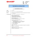
TROUBLE SHOOTING TABLE FOR PC I/F UNIT-11
Yes
Yes
Yes
Yes
No
No
No
No
Yes
No
Checking the DVI digital input
Feed the DVI digital signal to
INPUT3.
INPUT3.
Select the INPUT3 input.
Is the image free of distortion?
Are the colors as specified?
Does image appear onscreen?
No problem with the DVI
digital input.
digital input.
Is the sync signal as specified?
Is the clock as specified?
IC298 (Sil151) or its
peripherals defective.
peripherals defective.
IC298 (Sil151) or its
peripherals defective.
peripherals defective.
IC298 (Sil151) or its
peripherals defective.
peripherals defective.
Note:
In order to establish the plug & play fashion, first connect the cable
to INPUT3 and then turn on the computer power (signal generator).
In order to establish the plug & play fashion, first connect the cable
to INPUT3 and then turn on the computer power (signal generator).
»
Measure the C463 land for the vertical sync
signal and the C464 land for the horizontal sync
signal (on the back the PC board).
signal and the C464 land for the horizontal sync
signal (on the back the PC board).
»
Measure the R685 value for the clock (on the
back of the PC board).
back of the PC board).
58
XG-V10WE
AN-SD1E/S422E
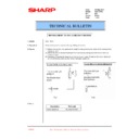
TROUBLE SHOOTING TABLE FOR PC I/F UNIT-12
Yes
Yes
Yes
Yes
Yes
Yes
No
No
No
No
No
No
Checking the DVI analog input
3
With the plug & play fashion
established, feed the DVI
analog signal to INPUT3.
established, feed the DVI
analog signal to INPUT3.
Select the INPUT3 input.
Does image appear onscreen?
DVI connector or its
peripherals defective.
peripherals defective.
CVIC_IC or IC4 peripherals
defective.
defective.
IC302 or its peripherals
defective.
defective.
Check the DVI_SOG circuit.
Sync separation circuit IC330
or IC331 (TL712CPW) or its
peripherals defective.
or IC331 (TL712CPW) or its
peripherals defective.
Are there R, G and B signals?
(Check to see if the R, G and B
signals are coming to pins
(126), (136) and (141) of IC4.)
(Check to see if the R, G and B
signals are coming to pins
(126), (136) and (141) of IC4.)
Is the image free of distortion?
Is the sync signal of separate
type?
type?
Are there horizontal and
vertical sync signals at TL130
and TL131?
vertical sync signals at TL130
and TL131?
Is the sync signal as specified?
(Check pin (6) of IC330 for the
vertical sync signal and pin (6)
of IC331 for the horizontal sync
signal.)
(Check pin (6) of IC330 for the
vertical sync signal and pin (6)
of IC331 for the horizontal sync
signal.)
59
XG-V10WE
AN-SD1E/S422E
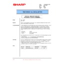
TROUBLE SHOOTING TABLE FOR PC I/F UNIT-13
Yes
Yes
Yes
Yes
No
No
No
No
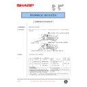
Checking the DVI_SOG
Is there horizontal sync signal
at TL82?
at TL82?
Is there Green signal at pin
(135) of IC4?
(135) of IC4?
IC4 or IIC bus control
peripherals defective.
peripherals defective.
Is there sync signal at TL136?
IC23 or IC336 defective.
Are pins (4) of IC23 and IC336
at low level?
at low level?
DVI connector or its
peripherals defective.
peripherals defective.
CPU port defective.
No problem with the DVI_SOG.
»
The SOG component of the DVI analog signal is separated
in the CXA3516R circuit. The Green signal is fed to the
SOGIN2 terminal. The DVI SOG sync signal is selected
by the bus switch (IC23).
in the CXA3516R circuit. The Green signal is fed to the
SOGIN2 terminal. The DVI SOG sync signal is selected
by the bus switch (IC23).


