Sharp MX-M623U / MX-M753U (serv.man10) Service Manual ▷ View online
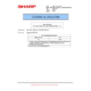
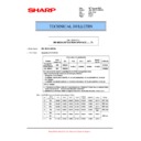
MX-M753N SIMULATION 6 – 29
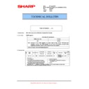
27-14
Purpose
Setting
Function (Purpose) Used to set the FSS function connection
test mode.
Section
Operation/Procedure
1)
1)
Enter the set value with 10-key.
2)
Press [OK] key.
The set value in step 1) is saved.
The set value in step 1) is saved.
* For setting the FSS function connection test mode, only DIS-
ABLE to ENABLE can be made. (ENABLE to DISABLE cannot
be made.)
be made.)
30
30-1
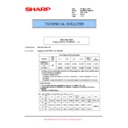
Purpose
Operation test/check
Function (Purpose) Used to check the operations of the sen-
sors and the detectors in other than the
paper feed section and the control circuits.
paper feed section and the control circuits.
Section
Operation/Procedure
The operating conditions of the sensors and detectors are dis-
played.
The sensors and the detectors which are turned ON are high-
lighted.
The operating conditions of the sensors and detectors are dis-
played.
The sensors and the detectors which are turned ON are high-
lighted.
30-2
Purpose
Operation test/check
Function (Purpose) Used to check the operations of the sen-
sors and the detectors in the paper feed
section and the control circuits.
section and the control circuits.
Section
Operation/Procedure
The operating conditions of the sensors and detectors are dis-
played.
The sensors and the detectors which are turned ON are high-
lighted.
The operating conditions of the sensors and detectors are dis-
played.
The sensors and the detectors which are turned ON are high-
lighted.
33
33-1
Purpose
Operation test/check
Function (Purpose) Used to check the operations of the card
reader sensor and the control circuit.
Section
Operation/Procedure
The operating conditions of the sensors and detectors are dis-
played.
The sensors and the detectors which are turned ON are high-
lighted.
The operating conditions of the sensors and detectors are dis-
played.
The sensors and the detectors which are turned ON are high-
lighted.
33-2
Purpose
Data clear
Function (Purpose) Used to delete the ID (IDM) information of
card.
Section
Operation/Procedure
1)
1)
Press [EXECUTE] key.
2)
Press [YES] key.
The ID (IDM) information of Felica card in the HDD is deleted.
The ID (IDM) information of Felica card in the HDD is deleted.
0
Disable (Default)
1
Enable
PPD
Resist detection
PFD2
Paper feed transport detection
POD1
Fusing rear detection
POD2
Main unit paper exit detection
POD3
Main unit paper exit full detection
LPPD
LCC paper pass detection
WEBEND1
Web end detection 1
WEBEND2
Web end detection 2
DSW_L
Left door open/close detection
DSW_F
Front door open/close detection
DSW_DSK
Desk left door open/close detection
TNFS
Waste toner full detection
TLS
Waste toner lock detection
THPS
Transfer belt home position detection
TANSET
Tray 1, 2 insertion detection
T1PPD
Tray 1 paper pass detection
T1LUD
Tray 1 paper upper limit detection
T1PED
Tray 1 paper empty detection
T1SPD
Tray 1 paper remaining quantity detection
MPRD1
Manual paper feed interface paper detection 1
MPRD2
Manual paper feed interface paper detection 2
T2LUD
Tray 2 paper upper limit detection
T2PED
Tray 2 paper empty detection
T2SPD
Tray 2 paper remaining quantity detection
M1SS1
Tray 3 rear edge detection 1
M1SS2
Tray 3 rear edge detection 2
M1SS3
Tray 3 rear edge detection 3
M1SS4
Tray 3 rear edge detection 4
M2SS1
Tray 4 rear edge detection 1
M2SS2
Tray 4 rear edge detection 2
M2SS3
Tray 4 rear edge detection 3
M2SS4
Tray 4 rear edge detection 4
M1PFD
Tray 3 paper pass detection
M1LUD
Tray 3 paper upper limit detection
M1PED
Tray 3 paper empty detection
M1SPD
Tray 3 paper remaining quantity detection
M2PFD
Tray 4 paper pass detection
M2LUD
Tray 4 paper upper limit detection
M2PED
Tray 4 paper empty detection
M2SPD
Tray 4 paper remaining quantity detection
MPFD1
Paper pass detection 1 from manual paper feed tray
MPFD2
Paper pass detection 2 from manual paper feed tray
MPED
Manual paper feed paper empty detection
MPLD1
Manual paper feed length detection 1
MPLD2
Manual paper feed length detection 2
MTOP1
Manual paper feed pulling detection 1
MTOP2
Manual paper feed pulling detection 2
DSW_R
Manual paper feed open/close detection
CARD
Card Yes/No detection
DATA
Card number signal detection
CLOCK
Reference clock signal detection
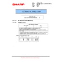
MX-M753N SIMULATION 6 – 30
40
40-2
Purpose
Adjustment/Setting
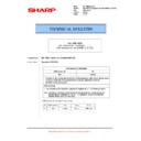
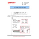
Function (Purpose) Manual paper feed tray paper width sensor
adjustment.
Section
Paper feed
Operation/Procedure
1)
1)
Open the manual paper feed guide to the max. width (MAX).
2)
Press [EXECUTE] key.
The max. width (MAX) detection level is recognized.
The max. width (MAX) detection level is recognized.
3)
Open the manual paper feed guide to P1 width (A4R).
4)
Press [EXECUTE] key.
The P1 width (A4R) detection level is recognized.
The P1 width (A4R) detection level is recognized.
5)
Open the manual paper feed guide to P2 width (A5R).
6)
Press [EXECUTE] key.
The P2 width (A5R) detection level is recognized.
The P2 width (A5R) detection level is recognized.
7)
Open the manual paper feed guide to the min. width (MIN).
8)
Press [EXECUTE] key.
The min. width (MIN) detection level is recognized.
The min. width (MIN) detection level is recognized.
When the above operation is not performed normally, "ERROR" is
displayed. When completed normally, "COMPLETE" is displayed.
displayed. When completed normally, "COMPLETE" is displayed.
40-7
Purpose
Adjustment/Setting
Function (Purpose) Used to set the adjustment value of the
manual paper feed tray paper width sensor.
Section
Paper feed
Operation/Procedure
1)
1)
Select a target item to be adjusted with [
] [] buttons.
2)
Enter the set value with 10-key.
3)
Press [OK] key.
The set value in step 2) is saved.
The set value in step 2) is saved.
40-12
Purpose
Adjustment/Setting
Function (Purpose) Used to adjust the multi-purpose tray width
detection level.
Section
Paper feed
Operation/Procedure
1)
1)
Open the multi-purpose tray guide to the maximum width, and
press [EXECUTE] key.
The maximum detection level is recognized.
press [EXECUTE] key.
The maximum detection level is recognized.
2)
When the minimum width adjustment start is displayed, open
the guide to the minimum width and press [EXECUTE] key.
The minimum detection level is recognized.
the guide to the minimum width and press [EXECUTE] key.
The minimum detection level is recognized.
41
41-1
Purpose
Operation test/check
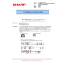
Function (Purpose) Used to check the operations of the docu-
ment size sensor and the control circuit.
Section
Operation/Procedure
The operating conditions of the sensors and detectors are dis-
played.
The sensors and the detectors which are turned ON are high-
lighted.
The operating conditions of the sensors and detectors are dis-
played.
The sensors and the detectors which are turned ON are high-
lighted.
41-2
Purpose
Adjustment
Function (Purpose) Used to adjust the document size sensor
detection level.
Section
Operation/Procedure
1)
1)
Open the document cover, and press [EXECUTE] key without
place a document on the document table.
The sensor level without document is recognized.
place a document on the document table.
The sensor level without document is recognized.
2)
Set A3 (11” x 17") paper on the document table, and press
[EXECUTE] key.
The sensor level when detecting the document is displayed.
[EXECUTE] key.
The sensor level when detecting the document is displayed.
When the above operation is normally completed, it is displayed.
41-3
Purpose
Operation test/check
Function (Purpose) Used to check the operations of the docu-
ment size sensor and the control circuit.
Section
Operation/Procedure
The detection output level (A/D value) of OCSW and the document
sensor (PD1 - PD7) is displayed in real time.
The light receiving range of PD1 - PD7 is 1 - 255. (Default: 128)
The detection output level (A/D value) of OCSW and the document
sensor (PD1 - PD7) is displayed in real time.
The light receiving range of PD1 - PD7 is 1 - 255. (Default: 128)
43
43-1
Purpose
Setting
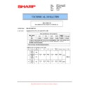
Function (Purpose) Used to make the fusing reference temper-
ature setting 1 in each operation mode.
Section
Operation/Procedure
1)
1)
Select an item to be set with [
] [] keys.
2)
Enter the set value with 10-key.
3)
Press [OK] key.
The set value in step 2) is saved.
The set value in step 2) is saved.
MAX POSITION
Manual feed max. width
P1(A4R)POSITION
Manual feed P1 position width (A4R)
P2(A5R)POSITION
Manual feed P2 position width (A5R)
MIN POSITION
Manual feed min. width
Item/Display
Content
Default
value
A
MAX POSITION
Manual feed max. width
193
B
P1 POSITION
Manual feed P1 position width (A4R)
183
C
P2 POSITION
Manual feed P2 position width (A5R)
133
D
MIN POSITION
Manual feed min. width
84
OCSW
Document cover status
Open: Normal display
Close: Highlighted
Close: Highlighted
PD1 - 7
Document detection
sensor status
sensor status
No document: Normal display
Document present: Highlighted
Document present: Highlighted
Item/Display
Content
Detection level range
OCSW
Original cover SW
0-1 ("1" to Close)
PD1 - PD7
Document detection 1 -
Document detection 7
Document detection 7
0 - 255
MX-M753N SIMULATION 6 – 31
NOTE: The set value may be changed for a design change or an individual arrangement. Except for the above cases, however, the set value
must not be changed. If it is changed, a trouble may be occur.
<Code descriptions>
<List of destination groups>
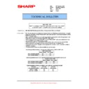
43-4
Purpose
Setting
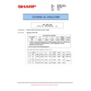
Function (Purpose) Used to set the fusing temperature 2 in
each operation mode.
Section
Operation/Procedure
1)
1)
Select an item to be set with [
] [] keys.
2)
Enter the set value with 10-key.
3)
Press [OK] key.
The set value in step 2) is saved.
The set value in step 2) is saved.
NOTE: The set value may be changed for a design change or an
individual arrangement. Except for the above cases, how-
ever, the set value must not be changed. If it is changed, a
trouble may be occur.
ever, the set value must not be changed. If it is changed, a
trouble may be occur.
Item
Display
Content
Setting
range
Default value
Group A
Group B
Group C
SW-A
SW-B
SW-A
SW-B
SW-A
SW-B
A
HL_UM READY
TH_UM set value when ready standby
70 - 240
200
205
200
205
200
205
B
HL_US READY
TH_US set value when ready standby
70 - 240
200
205
200
205
200
205
C
HL_UM PLAIN PAPER BW
Black and white plain paper TH_UM set value
70 - 240
200
205
210
210
D
HL_US PLAIN PAPER BW
Black and white plain paper TH_US set value
70 - 240
200
205
210
210
E
WARMUP FUMON HL_UM T
Fusing motor previous rotation start TH_UM set value
30 - 240
190
50
50
F
WARMUP FUMOFF HL_UM T
Fusing motor previous rotation complete time
0 - 200
5
G
WARM UP END TIME
Warm-up complete time
0 - 200
28
50
28
50
28
50
H
HL_UM HEAVY PAPER
Heavy paper TH_UM set value
70 - 240
220
I
HL_US HEAVY PAPER
Heavy paper TH_US set value
70 - 240
220
J
HL_UM OHP PAPER
OHP-TH_UM set value
70 - 240
210
K
HL_US OHP PAPER
OHP-TH_US set value
70 - 240
210
L
HL_UM E-STAR
Preheating TH_UM set value
30 - 200
165
M
HL_US E-STAR
Preheating TH_US set value
30 - 200
165
N
PRE-JOB
Resetting from preheating TH_UM set value
30 - 240
180
190
190
O
HL_UM WARMUP_120L
TH_UM set value when warming up of 120
C or less
70 - 240
200
210
215
215
P
HL_US WARMUP_120L
TH_US set value when warming up of 120
C or less
70 - 240
200
210
215
215
Q
LO_WARMUP_TIME
O - P applying time (Timer from completion of Ready)
0 - 255
5
R
HL_UM WARMUP_120H
TH_UM set value when warming up of 120
C or above
70 - 240
200
210
215
215
S
HL_US WARMUP_120H
TH_US set value when warming up of 120
C or above
70 - 240
200
210
215
215
T
HI_WARMUP_TIME
R - S applying time (Timer from completion of Ready)
0 - 255
5
U
HI_WU_FM_ON_TMP
FM previous rotation start TH_US set value when
warming up of alpha
warming up of alpha
C or above
30 - 240
130
V
HI _WU_END_TIME
Warm-Up complete time when warming up of alpha
C
or above
0 - 200
28
50
28
50
28
50
W
HI_WU_JOB_SET_TMP1
Job enable TH UM temperature 1 when warming up of
alpha
alpha
C or above
70 - 240
190
200
210
210
X
HI_WARMUP_BORDER
U - W applying set value
1 - 119
70
Y
LO_WU_JOB_SET_TMP1
Job enable TH UM temperature 1 when warming up of
alpha
alpha
C or less
70 - 240
190
200
210
210
Z
JOBEND_FUMON_TIME
After rotation time when Job end
0 - 200
10
AA
HI_WU_JOB_SET_TMP2
Job enable TH UM temperature 2 when warming up of
alpha
alpha
C or above
70 - 240
195
205
210
210
AB
LO_WU_JOB_SET_TMP2
Job enable TH UM temperature 2 when warming up of
alpha
alpha
C or less
70 - 240
195
205
210
210
TH_UM
Fusing upper thermistor main
HL_UM
Heater lamp upper main
TH_US
Fusing upper thermistor sub
HL_US
Heater lamp upper sub
SW-A
Setting value when 60 - 89g/m
2
SW-B
Set value when 90 - 105g/m
2
The set value displayed in this simulation differs depending on
60 - 89g/m
60 - 89g/m
2
or 90 - 105g/m
2
(Example) When 60 - 89g/m
2
Group
Destination
Group A
Japan
China
AB_B
Group B
U.S.A.
Canada
Inch
Group C
Europe
U.K.
AUS
AB_A
MX-M753N SIMULATION 6 – 32
<Code descriptions>
<List of destination groups>
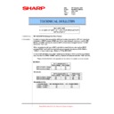
43-20
Purpose
Adjustment/Setting
Function (Purpose) Used to set the environmental correction
under low temperature and low humidity (L/
L) for the fusing temperature setting (SIM
43-1) in each paper mode.
L) for the fusing temperature setting (SIM
43-1) in each paper mode.
Section
Operation/Procedure
1)
1)
Select an item to be set with [
] [] keys.
2)
Enter the set value with 10-key.
3)
Press [OK] key.
The set value in step 2) is saved.
The set value in step 2) is saved.
NOTE: The set value may be changed for a design change or an
individual arrangement. Except for the above cases, how-
ever, the set value must not be changed. If it is changed, a
trouble may be occur.
ever, the set value must not be changed. If it is changed, a
trouble may be occur.
Correction value: -49 - +49, 1 Count = 1
C change/1sec change
Item
Display
Content
Setting
range
Default value
Group A
Group B
Group C
SW-A
SW-B
SW-A
SW-B
SW-A
SW-B
A
HL_UM PLAIN PAPER BW DUP
Black and white plain paper duplex TH_UM set
value
value
70 - 240
200
205
210
210
B
HL_US PLAIN PAPER BW DUP
Black and white plain paper duplex TH_US set
value
value
70 - 240
200
205
210
210
C
PLAIN PAPER BW DUP APP CNT
Black and white plain paper duplex applying
number of sheets
number of sheets
0 - 60
0
D
HL_UM HEAVY PAPER BW DUP
Black and white heavy paper duplex TH_UM set
value
value
70 - 240
220
E
HL_US HEAVY PAPER BW DUP
Black and white heavy paper duplex TH_US set
value
value
70 - 240
220
F
HEAVY PAPER BW DUP APP CNT
Black and white heavy paper duplex applying
number of sheets
number of sheets
0 - 60
0
TH_UM
Fusing upper thermistor main
HL_UM
Heater lamp upper main
TH_US
Fusing upper thermistor sub
HL_US
Heater lamp upper sub
SW-A
Setting value when 60 - 89g/m
2
is selected in the system setting/device setting/fusing control setting.
SW-B
Set value when 90 - 105g/m
2
is selected in the system setting/device setting/fusing control setting.
The set value displayed in this simulation differs depending on
60 - 89g/m
60 - 89g/m
2
or 90 - 105g/m
2
which is selected in the system setting/device setting/fusing control setting.
(Example) When 60 - 89g/m
2
is selected in the system setting/device setting/fusing control setting, the value of SW-A is displayed.
Group
Destination
Group A
Japan
China
AB_B
Group B
U.S.A.
Canada
Inch
Group C
Europe
U.K.
AUS
AB_A
Correction value
-49
-25
-5
0
+5
+25
+49
Input value
1
25
45
50
55
75
99
Item
Display
Content
Setting
range
Default value
Group A
Group B
Group C
SW-A
SW-B
SW-A
SW-B
SW-A
SW-B
A
HL_UM READY LL
Correction value for TH_UM set value in ready
standby under LL environment
standby under LL environment
1 - 99
55
60
60
B
HL_US READY LL
Correction value for TH_US set value in ready
standby under LL environment
standby under LL environment
1 - 99
55
60
60
C
HL_UM PLAIN BW LL
Correction value for black and white plain paper
TH_UM set value under LL environment
TH_UM set value under LL environment
1 - 99
55
D
HL_US PLAIN BW LL
Correction value for black and white plain paper
TH_US set value under LL environment
TH_US set value under LL environment
1 - 99
55
E
WARMUP FUMON HL_US T LL
Correction value for fusing motor previous rotation
start TH_UM set value under LL environment
start TH_UM set value under LL environment
1 - 99
5
50
50
F
WARMUP FUMOFF T LL
Correction value for fusing motor previous rotation
completion time under LL environment
completion time under LL environment
1 - 99
50
G
WARMUP END TIME LL
Correction value for warm-up complete time under
LL environment
LL environment
1 - 99
80
H
HL_UM HEAVY LL
Correction value for heavy paper TH_UM set value
under LL environment
under LL environment
1 - 99
55
I
HL_US HEAVY LL
Correction value for heavy paper TH_US set value
under LL environment
under LL environment
1 - 99
55

