Sharp MX-2600N / MX-3100N / MX-2600G / MX-3100G (serv.man7) Service Manual ▷ View online
MX-3100N ADJUSTMENTS 6 – 84
(Method 2)
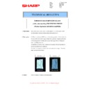
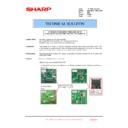
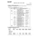
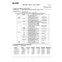
Use SIM67-25 to print the color balance adjustment sheet and
compare the black patch color balance of each process (CMY)
with the black patch. This procedure allows checking the color
balance adjustment result correctly.
Use SIM67-25 to print the color balance adjustment sheet and
compare the black patch color balance of each process (CMY)
with the black patch. This procedure allows checking the color
balance adjustment result correctly.
*1: In the case of the GDI printer, this section are not printed.
If the color balance of each patch of the process black (CMY
mixed color) is slightly shifted to Magenta, it means that the
adjustment is proper. If the color balance of the adjustment
pattern printed in this mode is slightly shifted to Magenta, it is
converted into the natural gray color balance by the color table
in an actual printer mode. (When the color balance target is
DEF 1.)
If a satisfactory result on the print color balance and the den-
sity is not obtained with the automatic adjustment, execute the
manual adjustment (SIM 67-25) (ADJ 21B).
ADJ 22
Adjusting the fusing paper
guide position
guide position
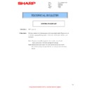
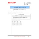
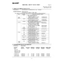
This adjustment is needed in the following situations:
* When the fusing section is disassembled.
* When a paper jam occurs in the fusing section.
* When a wrinkle is made on paper in the fusing section.
* When an image deflection or image blur occurs in the paper rear
* When the fusing section is disassembled.
* When a paper jam occurs in the fusing section.
* When a wrinkle is made on paper in the fusing section.
* When an image deflection or image blur occurs in the paper rear
edge section.
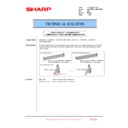
1)
Loosen the fixing screw C.
2)
Shift the fusing paper guide in the arrow direction A or B (up
and down direction).
and down direction).
The standard fixing position is the center of the marking scale.
Change the position depending on the situation.
* When a wrinkle is formed on paper, change the position
Change the position depending on the situation.
* When a wrinkle is formed on paper, change the position
upward (in the arrow direction A).
* When an image deflection or image blur occurs in the paper
rear edge section, shift the position downward (in the arrow
direction A).
direction A).
ADJ 23
Document size sensor
adjustment
adjustment
This adjustment is needed in the following situations:
* When the original size sensor section has been disassembled.
* When the original size sensor section has been replaced.
* When U2 trouble has occurred.
* When the scanner control PWB is replaced.
* When the EEPROM on the scanner control PWB is replaced.
* When the original size sensor section has been disassembled.
* When the original size sensor section has been replaced.
* When U2 trouble has occurred.
* When the scanner control PWB is replaced.
* When the EEPROM on the scanner control PWB is replaced.
23-A
Document size sensor detection point
adjustment
adjustment
1)
Go through the modes specified in Simulation 41-1.
;
/
%
$M
3
/CZ
1
2
0
/
.
-
,
+
*
)
(
'
&
%
$
#
CMY
Blend
Blend
High density
Low density
Patch A of each of Y, M, C, and
BK are not copied.
BK are not copied.
2) Patch C or D of each of Y, C, M, and
BK is very slightly copied.
3) Patch for each of C, M, Y, BK
The patch density is identical between patches or not reversed.
The patch density is changed gradually.
The patch density is changed gradually.
1) The max. density section is not blurred.
*1
A
B
C
A
B
C
ǂǂǂ6,08/$7,21ǂǂ12
&/26(
7(67
3'6(1625&+(&.
2&6:
3'
3'
3'
3'
3'
3'
3'
MX-3100N ADJUSTMENTS 6 – 85
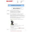
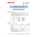
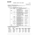
Loosen the original cover switch actuator adjustment screw
and slide the actuator position so that the display OCSW is
returned to the normal display when the height of the arm unit
top from the table glass is 32
and slide the actuator position so that the display OCSW is
returned to the normal display when the height of the arm unit
top from the table glass is 32
±0.5mm by slowly tilting the doc-
ument detection arm unit in the arrow direction and adjust.
(If the ON timing of the original cover switch is shifted, the doc-
ument detection function may malfunction.)
(If the ON timing of the original cover switch is shifted, the doc-
ument detection function may malfunction.)
23-B
Adjust the sensitivity of the original size
sensor
sensor
1)
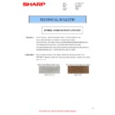
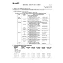
Enter the SIM41-2 mode.
2)
Execute the sensor adjustment without document.
With the document cover open, without placing a document on
the table glass, press [EXECUTE] key.
With the document cover open, without placing a document on
the table glass, press [EXECUTE] key.
3)
Place A3 (11" x 17") paper on the document table and press
[EXECUTE] key.
If the adjustment is completed normally, "DOCUMENT PHOTO
SENSOR LEVEL IS ADJUESTED" is displayed.
[EXECUTE] key.
If the adjustment is completed normally, "DOCUMENT PHOTO
SENSOR LEVEL IS ADJUESTED" is displayed.
32 0.5mm
+-
Adjustment completed
EXECUTE
Adjustment
failed
failed
EXECUTE
ǂǂǂ6,08/$7,21ǂǂ12
&/26(
7(67
'2&80(176,=(3+2726(16256(783
(;(&87(
ේⓂᬌ⍮ࡦ ࠨߩࡌ࡞ࠍ⺞ᢛߒ߹ߒߚޕ
ǂǂǂ6,08/$7,21ǂǂ12
&/26(
7(67
'2&80(176,=(3+2726(16256(783
(;(&87(
ࠝࠫ࠽ ࡞ࠞࡃࠍ㐿ߚ⁁ᘒߢࠟࠬ㕙ߦේⓂࠍ࠶࠻ߒߥߢ
=':'%76'?ࡏ࠲ࡦࠍߒߡߊߛߐޕ
ǂǂǂ6,08/$7,21ǂǂ12
&/26(
7(67
'2&80(176,=(3+2726(16256(783
(;(&87(
ࠟࠬ㕙 ߦ#
ࠨࠗ࠭ߩ↪⚕ࠍ࠶࠻ߒߡޔ
=':'%76'?ࡏ࠲ࡦࠍߒߡߊߛߐޕ
ǂǂǂ6,08/$7,21ǂǂ12
&/26(
7(67
'2&80(176,=(3+2726(16256(783
(;(&87(
ਅ⸥ߩේⓂ ᬌ⍮ࡦࠨߢ⺞ᢛਇ⦟߇⊒↢ߒ߹ߒߚޕ
2&
MX-3100N ADJUSTMENTS 6 – 86
ADJ 24
Manual paper feed tray paper
size (width) sensor adjustment
size (width) sensor adjustment
This adjustment is needed in the following situations:
* The manual paper feed tray section has been disassembled.
* The manual paper feed tray unit has been replaced.
* U2 trouble has occurred.
* The PCU PWB has been replaced.
* The EEPROM of the PCU PWB has been replaced.
1)
* The manual paper feed tray section has been disassembled.
* The manual paper feed tray unit has been replaced.
* U2 trouble has occurred.
* The PCU PWB has been replaced.
* The EEPROM of the PCU PWB has been replaced.
1)
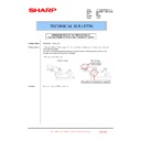
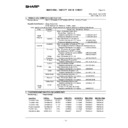
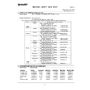
Go through the modes specified in Simulation 40-2.
2)
Open the manual paper feed guide to the maximum width posi-
tion.
tion.
3)
Press [EXECUTE] key.
[EXECUTE] key is highlighted. Then it returns to the normal
display.
The maximum width position detection level of the manual
paper feed guide is recognized.
[EXECUTE] key is highlighted. Then it returns to the normal
display.
The maximum width position detection level of the manual
paper feed guide is recognized.
4)
Set the manual paper feed guide to the A4 size.
5)
Press [EXECUTE] key.
[EXECUTE] key is highlighted. Then it returns to the normal
display.
The A4 size width position detection level of the manual paper
feed guide is recognized.
[EXECUTE] key is highlighted. Then it returns to the normal
display.
The A4 size width position detection level of the manual paper
feed guide is recognized.
6)
Set the manual paper feed guide to the width for the A4R size.
7)
Press [EXECUTE] key.
[EXECUTE] key is highlighted. Then it returns to the normal
display.
Set the manual paper feed guide to the width for the A4R size.
[EXECUTE] key is highlighted. Then it returns to the normal
display.
Set the manual paper feed guide to the width for the A4R size.
8)
Open the manual paper feed guide to the minimum width posi-
tion.
tion.
9)
Press [EXECUTE] key.
[EXECUTE] key is highlighted. Then it returns to the normal
display.
The minimum width position detection level of the manual
paper feed guide is recognized.
If the above operation is not completed normally, "ERROR" is
displayed.
When the operation is completed normally, the above data are
saved to the memory and "COMPLETE" is displayed.
EXECUTE
EXECUTE
Repeat the above procedure to adjust
the A4R width MIN POSITION.
the A4R width MIN POSITION.
ǂǂǂ6,08/$7,21ǂǂ12
&/26(
7(67
%<3$6675$<$'-8670(17
(;(&87(
0$;326,7,21$'-8670(17
35(66>(;(&87(@7267$57
ǂǂǂ6,08/$7,21ǂǂ12
&/26(
7(67
%<3$6675$<$'-8670(17
(;(&87(
0$;326,7,21$'-8670(17
(;(&87,1*
ǂǂǂ6,08/$7,21ǂǂ12
&/26(
7(67
%<3$6675$<$'-8670(17
(;(&87(
3$326,7,21$'-8670(17
35(66>(;(&87(@7267$57
ǂǂǂ6,08/$7,21ǂǂ12
&/26(
7(67
%<3$6675$<$'-8670(17
(;(&87(
&203/(7(
MX-3100N ADJUSTMENTS 6 – 87
ADJ 25
RSPF tray paper size (width)
sensor adjustment (RSPF
mode)
sensor adjustment (RSPF
mode)
1)
Enter the SIM 53-6 mode.
2)
Set the tray document guide to the max. width position, and
press [EXECUTE] key. The button is highlighted and the tray
size volume maximum value adjustment is started.
* During the adjustment, "EXECUTING..." is displayed.
* After completion of the tray size volume maximum value
press [EXECUTE] key. The button is highlighted and the tray
size volume maximum value adjustment is started.
* During the adjustment, "EXECUTING..." is displayed.
* After completion of the tray size volume maximum value
adjustment, the set value is saved to EEPROM and RAM
and the display is shifted to the tray volume A4R size adjust-
ment value start screen. (Each set value is saved to
EEPROM and RAM at each setting.)
and the display is shifted to the tray volume A4R size adjust-
ment value start screen. (Each set value is saved to
EEPROM and RAM at each setting.)
3)
Set the tray document guide to A4R width position and press
[EXECUTE] button. The pressed button is highlighted and the
tray A4R size adjustment is started.
[EXECUTE] button. The pressed button is highlighted and the
tray A4R size adjustment is started.
4)
Adjust the tray volume A5R size and the tray size volume min-
imum value according to the above procedures.
imum value according to the above procedures.
5)
Completion of the adjustment, "COMPLETE" is displayed. If
the adjustment is not completed normally for any reason,
"ERROR" is displayed. In that case, the adjustment must be
executed again.
the adjustment is not completed normally for any reason,
"ERROR" is displayed. In that case, the adjustment must be
executed again.
<Adjustment item and content>
When one of 1-4 in the above table is selected, the guide plate is
shifted to each position of the four widths of the guide plate shown
in the table below. The value of the document width sensor
(RSPF_WIDTH) A/D value is saved to EEPROM.
<Guide plate positions and widths on the mechanism and A/D val-
ues to be saved>
shifted to each position of the four widths of the guide plate shown
in the table below. The value of the document width sensor
(RSPF_WIDTH) A/D value is saved to EEPROM.
<Guide plate positions and widths on the mechanism and A/D val-
ues to be saved>
ADJ 26
Touch panel coordinate setting
This adjustment is needed in the following situations:
* The operation panel has been replaced.
* U2 trouble has occurred.
* The scanner control PWB has been replaced.
* The EEPROM on the scanner control PWB has been replaced.
1)
* The operation panel has been replaced.
* U2 trouble has occurred.
* The scanner control PWB has been replaced.
* The EEPROM on the scanner control PWB has been replaced.
1)
Enter the SIM 65-1 mode.
2)
Precisely press the cross mark points (4 positions).
When the cross mark is pressed precisely, a buzzer sounds
and the display is reversed. When all the four points are
pressed and the touch panel adjustment is completed, the dis-
play returns to the simulation sub number entry screen.
In case of an error, the display returns to the entry screen
again.
Check to confirm that there is no shift between the display
frame and the detection position when the touch panel is
pressed.
* When pressing the touch panel, never use a sharp tip (such
as a needle or a pin).
ADJ 27
Image loss, void area, image
off-center, image magnification
ratio auto adjustment with
SIM50-28
off-center, image magnification
ratio auto adjustment with
SIM50-28
The following adjustment items can be executed automatically with
SIM50-28.
* ADJ 8 Print image magnification ratio adjustment
SIM50-28.
* ADJ 8 Print image magnification ratio adjustment
(Main scanning direction) (Print engine section)
* ADJ 9 Image off-center adjustment (Print engine section)
* ADJ 14/15 Scan image magnification ratio adjustment
* ADJ 16 Scan image off-center adjustment
* ADJ 17 Print area (void area) adjustment (Print engine section)
* ADJ 18 Copy image position, image loss adjustment
(Menu in SIM50-28 mode)
* ADJ 14/15 Scan image magnification ratio adjustment
* ADJ 16 Scan image off-center adjustment
* ADJ 17 Print area (void area) adjustment (Print engine section)
* ADJ 18 Copy image position, image loss adjustment
(Menu in SIM50-28 mode)
NO.
Display
Content
1
TRAYVOLMAX
Tray size volume maximum value
2
TRAYVOLA4R
Tray volume A4R size adjustment value
3
TRAYVOLA5R
Tray volume A5R size adjustment
4
TRAYVOLMIN
Tray size volume minimum value
NO
Guide
plate
position
Widths on the mechanism
A/D
value,
code in
the figure
below
Remark
AB
series
INCH
series
Code in
the figure
below
1
Maximum
position
position
299
299
WIDTH
_MAX
_MAX
AD_MAX
2
Middle
position (L)
position (L)
210
215.9
WITH_P1
AD_P1
A4R OR
LTR
LTR
3
Middle
position (S)
position (S)
148.5
139.7
WITH_P2
AD_P2
A5R OR
INVR
INVR
4
Minimum
position
position
118
118
WITH_MIN
AD_MIN
ǂǂǂ6,08/$7,21ǂǂ12
&/26(
7(67
63)75$<$'-8670(17
(;(&87(
75$<92/0$;75$<$'-8670(17
35(66>(;(&87(@7267$57
Display/Item
Content
OC ADJ
Image loss off-center sub scanning direction
image magnification ratio adjustment
(Document table mode)
image magnification ratio adjustment
(Document table mode)
BK-MAG ADJ
Main scanning direction image magnification
ratio adjustment
ratio adjustment
SPF ADJ
Image loss off-center sub scanning direction
image magnification ratio adjustment
(RSPF mode)
image magnification ratio adjustment
(RSPF mode)
SETUP/PRINT ADJ
Print lead edge adjustment, image off-center
(each paper feed tray, duplex mode)
adjustment
(each paper feed tray, duplex mode)
adjustment
RESULT
Adjustment result display
DATA
Display of data used when an adjustment is
executed
executed

