Sharp MX-2600N / MX-3100N / MX-2600G / MX-3100G (serv.man104) Service Manual / Technical Bulletin ▷ View online
Date:
19
th
March 2009
Model:
MX2600N – MX3100N
Ref.:
015
Colour:
White
Page:
1 0f 8
TECHNICAL BULLETIN
INSTALLATION MANUAL REVISION.
Sharp Electronics (UK) Ltd., Technical Services Group
CCE-611
1. Model Name:
MX-2600N – MX3100N
2. General:
We will notify you of revised locations in the installation manual.
(Main reasons for revision)
- Modification of image quality adjustment method
- Addition of notes
- Addition of notes
3. Description:
See the accompanying materials for details.
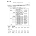
MX-3100N MX-2600N/3100N, MX-2600G/3100G 1 – 10
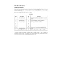
J. Specifications setup
Used to set the specifications with SIM26 according to the cus-
tomer's request.
tomer's request.
To customize the following items after completion of the destination
setup, change the set values.
setup, change the set values.
K. Image quality check
(Image Quality Check Flowchart)
Step 1: Image Skew Check
Perform Simulation 50-22 (select "ALL").
If Image Skew is "OK" for all Colors, proceed to Step 2.
If Image Skew is "NG" for any Colors, Proceed to Black Laser
Skew Adjustment Procedure.
Skew Adjustment Procedure.
When complete, go back to Simulation 50-22 (select "ALL"), and
make Color Laser Skew adjustments as shown on machine dis-
play. Repeat until proper specification is reached. When Color
Laser Skew Adjustment is complete, proceed to Step 2.
make Color Laser Skew adjustments as shown on machine dis-
play. Repeat until proper specification is reached. When Color
Laser Skew Adjustment is complete, proceed to Step 2.
Step 2: Image Loss, Void Area, Image Off-center adjustment
Perform Simulation 50-28.
Complete all of the adjustments as listed in order. When Adjust-
ments are complete, proceed to Step 3.
ments are complete, proceed to Step 3.
Step 3: Copy/Printer Color Balance Adjustment
Perform Simulation 46-74.
Summary of adjustments, please perform in order to achieve the
best quality results.
best quality results.
(1)
Checking and adjustment of the image skew
1)
Press [REGIST] button in SIM50-22 mode to execute the auto-
matic image registration adjustment.
matic image registration adjustment.
2)
The current skew level is displayed on the SKEW display
menu.
menu.
3)
Put down the displayed skew level value.
* When the machine is displays an "NG" condition for color laser
skew check/adjustment as well all colors laser skew adjustments
must to be checked or performed.
must to be checked or performed.
(Meaning of the skew level value)
* When "R" is displayed in front of the value, turn and click the
skew adjustment screw (LSU) clockwise by the number of the
value.
value.
* When "L" is displayed in front of the value, turn and click the
skew adjustment screw (LSU) counterclockwise by the number
of the value.
of the value.
At that time, the fractional part after the decimal point is rounded.
NOTE: The K (black) image skew level cannot be checked with
this adjustment.
To check and adjust the K (black) image skew, follow the
procedures below and execute the adjustment.
procedures below and execute the adjustment.
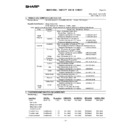
1)
Enter SIM61-4 mode.
2)
Select the paper feed tray with A3 (11" x 17") paper in it by
changing the value of set item B.
changing the value of set item B.
3)
Press [EXECUTE] key.
The check pattern is printed out.
4)
Check the printed black image for any skew.
Measure the right angle level by using the six cross patterns
printed in black.
printed in black.
There are following two methods of checking the black image
for any skew (right angle).
for any skew (right angle).
Method 1:
Measure the length of the diagonal lines of the rectangle print
pattern. Check the difference in the length of the diagonal lines
for judgment of good or no good
Measure the length of the diagonal lines of the rectangle print
pattern. Check the difference in the length of the diagonal lines
for judgment of good or no good
Method 2:
Compare the right angle of vertical side/horizontal side of the
rectangle print pattern and the right angle sides of A3 or 11 x
8.5 paper for judgment of good or no good.
Compare the right angle of vertical side/horizontal side of the
rectangle print pattern and the right angle sides of A3 or 11 x
8.5 paper for judgment of good or no good.
(NOTE) In the case of Method 2, the right angle of paper to be
used may not be exact. Be sure to check the right angle of
paper to be used in advance.
used may not be exact. Be sure to check the right angle of
paper to be used in advance.
(Method 1)
a) Measure the length of the diagonal lines of the rectangle
print pattern.
print pattern.
SIM No
Content
26
6
Used to set the destination.
SIM No
Content
26
2
LCC paper size setting
3
Used to set the auditor specification mode.
5
Used to set the count mode of the total counter and
the maintenance counter.
the maintenance counter.
18
Used to set YES/NO of the toner save mode (Only
in UK and Japan versions)
* For other destination versions, this setup is
in UK and Japan versions)
* For other destination versions, this setup is
made by the user program.
52
Used to set YES/NO of counting when non-print
paper is passed through each counter.
paper is passed through each counter.
53
Used to set YES/NO of user calibration permission.
65
Used to set the limit number of sheets for stapling.
1
or end of print
EXECUTE
EXECUTE
㪈㪇
ǂǂǂ6,08/$7,21ǂǂ12
&/26(
7(67
/68326,7,21$'-8670(176(/)35,17
$˖
˷̚˹
˖08/7,&2817
$˖
˖3$3(5&6
%˖
2.
(;(&87(
ǂǂǂ6,08/$7,21ǂǂ12
&/26(
7(67
/68326,7,21$'-8670(176(/)35,17
$˖
˷̚˹
˖08/7,&2817
$˖
˖3$3(5&6
%˖
2.
(;(&87(
key
4
(
Diagonal line D
Diagonal line C
: '08 Oct 15
1
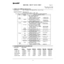
MX-3100N MX-2600N/3100N, MX-2600G/3100G 1 – 11
b) Calculate the difference between the measured lengths C
and D of the diagonal lines.
and D of the diagonal lines.
c) Check to insure that the difference between C and D is in
the following range. C – D =
the following range. C – D =
r0.8mm
If the difference between C and D is in the above range, there
is no need to adjust.
is no need to adjust.
(Method 2)
a) Fit the side of A3 or 11" x 17" paper to the long side of the
rectangle print pattern.
rectangle print pattern.
b) Measure the shift distance between vertical side of paper
and side of the rectangle print pattern.
and side of the rectangle print pattern.
If the above distance is 0.5mm or less, there is no need to
adjust.
adjust.
If not, execute the following procedures.
5)
Open the front cabinet, and remove the waste toner box.
6)
Loosen the LSU unit fixing screws (2 pcs.) and shift the skew
adjustment screw in the arrow direction to adjust the LSU (writ-
ing) unit skew.
adjustment screw in the arrow direction to adjust the LSU (writ-
ing) unit skew.
(When Method 1 is used to check the black image for any
skew (right angle) in procedure 4 in advance)
skew (right angle) in procedure 4 in advance)
When the lengths of the diagonal line are C > D, shift the
adjustment screw in the direction of Y.
adjustment screw in the direction of Y.
When the lengths of the diagonal line are C < D, shift the
adjustment screw in the direction of X.
adjustment screw in the direction of X.
(When Method 2 is used to check the black image for any
skew (right angle) in procedure 4 in advance)
skew (right angle) in procedure 4 in advance)
If the image is skewed in the arrow direction of A, shift the
adjustment screw to X direction. If the image is skewed in the
arrow direction of B, shift the adjustment screw to Y direction.
adjustment screw to X direction. If the image is skewed in the
arrow direction of B, shift the adjustment screw to Y direction.
7)
Install the waste toner box, and close the front cabinet.
8)
Execute procedures 3) - 4).
(Repeat procedures 5) - 8) until a satisfactory result is
obtained.)
obtained.)
9)
If the adjustment result reaches the satisfactory level, tighten
the adjustment screw.
the adjustment screw.
(The black image skew adjustment is completed with the
above.)
above.)
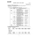
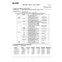
10) In the above black image skew adjustment, check the color
image skew pattern printed when completion of the adjust-
ment.
ment.
*A: Rough adjustment print pattern
*B: Fine adjustment print pattern
*B: Fine adjustment print pattern
In each Y/M/C color print pattern printed separately in the front
frame direction and in the rear frame direction, note the same
print color pattern and check to confirm that the difference in
the highest density sections is within
frame direction and in the rear frame direction, note the same
print color pattern and check to confirm that the difference in
the highest density sections is within
r1 step.
(Compare the front and the rear frame positions of the same-
color print color patterns. All the highest density sections of all
the print color patterns may not be aligned on a line. Compare
only the same-color patterns.)
color print color patterns. All the highest density sections of all
the print color patterns may not be aligned on a line. Compare
only the same-color patterns.)
If the above condition is not met, do the following:
11) Turn the image skew adjustment screw of the target color to
adjust.
When each adjustment screw is turned, it clicks. Turn it by
5 - 6 clicks and the check pattern is changed by 1 step (1
dot size).
5 - 6 clicks and the check pattern is changed by 1 step (1
dot size).
When the image skew pattern on the front frame side is
skewed in the arrow direction of A (to the smaller number) from
the rear frame side, turn the adjustment screw counterclock-
wise. When the image is skewed in the arrow direction of B (to
the larger number), turn the adjustment screw clockwise.
skewed in the arrow direction of A (to the smaller number) from
the rear frame side, turn the adjustment screw counterclock-
wise. When the image is skewed in the arrow direction of B (to
the larger number), turn the adjustment screw clockwise.
12) Print the check pattern.
13) Check the color image skew pattern.
Repeat procedures 11) - 13) until a satisfactory result is obtained.
The image skew adjustment (LSU unit) is executed by changing
the parallelism of the LSU unit scan laser beam for the OPC drum.
the parallelism of the LSU unit scan laser beam for the OPC drum.
1
4
(
A3 or 11 x 17 paper
0.5mm or less
Comparison line
Direction
B
Direction
A
X
Y
4
(
Cy
an
an
*A
Direction B
Direction A
Magenta
Y
ello
w
*B
*B
C
Y
M
: '08 Oct 15
1
MX-3100N MX-2600N/3100N, MX-2600G/3100G 1 – 12
(2)
Image registration adjustment
1)
Enter SIM50-22 mode.
2)
Select the adjustment target item "ALL".
ALL:
Image registration (Auto adjustment of the main scanning
direction, the sub scanning direction and the OPC drum
phase)
Image registration (Auto adjustment of the main scanning
direction, the sub scanning direction and the OPC drum
phase)
3)
Press [EXECUTE] key.
The adjustment are executed automatically and adjustment
result data is displayed.
result data is displayed.
4)
Check the image registration.
NOTE: For details of the checking procedures of the image regis-
tration, refer to the ADJ10B and the ADJ10C.
tration, refer to the ADJ10B and the ADJ10C.
(3)
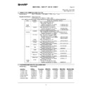
Image loss, void area, image off-center adjustment
Make a copy in the original table mode and in the RSPF/DSPF
mode. Check to confirm that the image loss and the void area are
in the range shown below.
mode. Check to confirm that the image loss and the void area are
in the range shown below.
NOTE: For details of the checking procedures of the image loss
and the void area, refer to the ADJ17 and the ADJ18.
and the void area, refer to the ADJ17 and the ADJ18.
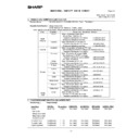
(Adjustment procedure)
a. Image off-center automatic adjustment
(in original table mode)
1)
Enter the SIM50-28 mode.
2)
Select [SETUP/PRINT] ADJ with the key button.
3)
Select [ALL] with the key button.
(Note)
By pressing [LEAD] or [OFFSET] button, the following items
can be executed individually.
can be executed individually.
* [LEAD]: Print image lead edge image position adjustment
* [OFFSET]: Print image off-center adjustment
When [ALL] is selected, both of the above two items are
executed simultaneously.
executed simultaneously.
4)
Select a paper feed tray to be adjusted.
(Select all of paper feed trays.)
(Select all of paper feed trays.)
* Ensure paper is in all trays for proper adjustment.
5)
Press [EXECUTE] key.
The adjustment pattern is printed out.
(Each paper is fed from selected paper feed tray, and the indi-
vidual pattern according to each paper feed tray is printed out.)
vidual pattern according to each paper feed tray is printed out.)
6)
Set the adjustment pattern on the document table. (Any direc-
tion)
tion)
NOTE: Fit the adjustment pattern correctly with the document
guide.
7)
Press [EXECUTE] key.
The following item is automatically adjustment.
* Print image lead edge image position adjustment
* Print image off-center adjustment
Perform procedures 6) to 7) for adjustment patterns output
from each paper feed tray.
from each paper feed tray.
8)
Press [OK] key.
The adjustment result becomes valid.
Perform procedures 4) to 7) for each paper feed tray.
Content
Standard adjustment value
Lead edge void area
3.0
r1.0mm
Rear edge void area
2.0 - 5.0mm
FRONT/REAR void area
2.0
r2.0mm
Lead edge image loss adjustment
3.0
r1.0mm
Side image loss adjustment
2.0
r1.0mm
1
ǂǂǂ6,08/$7,21ǂǂ12
&/26(
7(67
$872,0$*(326,7,21$'-8670(176(59,&(
2&ǂ$'-
%.0$*ǂ$'-
63)ǂ$'-
6(78335,17ǂ$'-
5(68/7
'$7$
ǂǂǂ6,08/$7,21ǂǂ12
&/26(
7(67
$872,0$*(326,7,21$'-8670(176(59,&(
/($'
2))6(7
$//
ǂǂǂ6,08/$7,21ǂǂ12
&/26(
7(67
$872,0$*(326,7,21$'-8670(176(59,&(
(;(&87(
0)7
&6
$'8
&6
&6
&6
/&&
: '08 Oct 15
1
Display

