Sharp AR-651 (serv.man6) Service Manual ▷ View online
AR-651/810 COMPONENT LAYOUT & FUNCTIONS 2 - 29
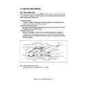
2. 6. 2. PC boards
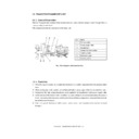
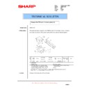
[A] System control board (SYS board)/Hard disk/
Logic board (LGC board)
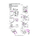
(1) Remove the rear cover.
(2) Disconnect 1 connector.
(3) Remove 2 screws (shown by 2 white arrows),
loosen 14 screws and take off the rear feed
side inner cover (plate cover).
(4) Remove 1 screw (shown by a white arrow),
loosen 8 screws and take off the rear exit
side inner cover (plate cover).
Rear feed side
inner cover
inner cover
Rear exit side
inner cover
inner cover
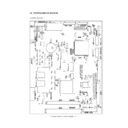
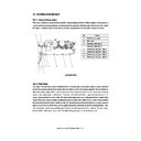
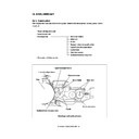
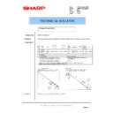
(5) Disconnect 7 connectors, remove 6 screws
and take off the SYS board.
(6) Disconnect 2 connectors, remove 4 screws
and take off the hard disk with the bracket.
(7) Remove 4 screws and release the hard disk
from the bracket.
(8) Disconnect 19 connectors, remove 6 screws
and take off the LGC board.
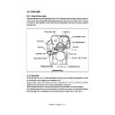
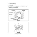
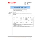
[B] High-voltage transformer
(1) Disconnect 7 connectors to the SYS board
and hard disk.
(2) Remove 9 screws and take off the bracket
with the LGC board and hard disk.
SYS board
Hard disk
SYS board
Hard disk bracket
LGC board
AR-651/810 COMPONENT LAYOUT & FUNCTIONS 2 - 30
(3) Disconnect 19 connectors to the LGC board.
(4) Remove 6 screws and take off the bracket
with the LGC board.
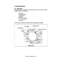
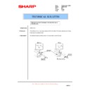
[C] Power supply unit
(1) Remove the SYS board, hard disk and LGC
board with the bracket.
(2) Remove 4 screws and take off the bracket of
the power supply unit.
(5) Disconnect 6 connectors, remove 1 screw,
release 3 lock supports and take off the high
voltage transformer.
(3) Disconnect 1 link connector.
(4) Remove 9 connectors and pull out the power
supply unit.
Note: Be careful not for the power supply unit to be
caught by harnesses.
LGC board
High-voltage transformer
Lock support
Link connector (3)

