Sharp AR-651 (serv.man16) Service Manual ▷ View online
AR-651/810 TRANSFER/TRANSPORT UNIT 13 - 9
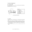
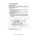
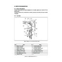
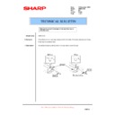
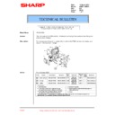
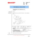
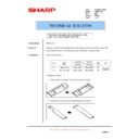
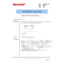
[G] Transport detection sensor
(1) Remove the transfer belt and fuser unit.
(2) Disconnect 1 connector, remove 1 screw and
take off each sensor.
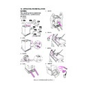
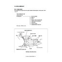
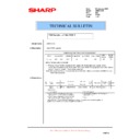
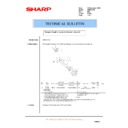
(H-2) Drive clutch
(1) Remove 1 E-ring and 3 screws and release the
bracket.
(2) Disconnect 1 connector and take off the drive
clutch.
Notes: 1. When installing the clutches, pay attention
to the color of harness.
2. When fitting the E-rings on the clutches, make
sure that the latches of E-ring do not
protrude on the flat part of shaft.
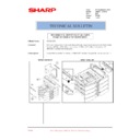
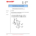
[H] Transport clutch
(H-1) Transport clutch 1, 2
(1) Disconnect 1 connector, remove 1 E-ring and
take off each transport clutch.
Notes: 1. When installing the clutches, pay attention
to the color of harness.
2. Make sure that the E-rings are tightly fit not
to be loosen and one end of E-ring does not
ride too much on the flat part of shaft.
E-ring
Transport clutch 1
Transport clutch 2
E-ring
Bracket
Black
Drive clutch
AR-651/810 TRANSFER/TRANSPORT UNIT 13 - 10
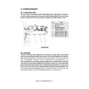
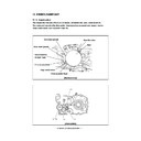
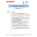
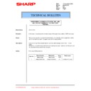
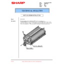
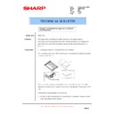
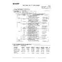
[I] Transfer belt drive motor unit
(1) Remove the rear cover and take off the flywheel.
(2) Disconnect 1 connector, remove 1 spring
and 2 screws and take off the drive motor unit.
Note: When installing the motor, rotate it counterclock-
wise to fix.
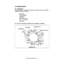
Green board
Silver board
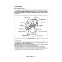
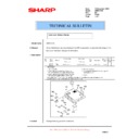
[J] Transfer belt contact/release cam drive unit
(1) Remove the rear cover and take off the flywheel.
(2) Disconnect 1 connector, remove 2 screws and
take off the cam drive unit.
(3) Disconnect the connector and take off 2 sensors.
Note: When replacing each sensor, pay attention to
the board color (shown in the right figure) and
direction.
Spring
Connector

