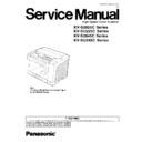
Panasonic KV-S2025C / KV-SU225C / KV-S2045C / KV-SU245C Service Manual ▷ View online
KV-S2025C Series
KV-SU225C Series
KV-S2045C Series
KV-SU245C Series
KV-SU225C Series
KV-S2045C Series
KV-SU245C Series
High Speed Color Scanner
ORDER NO. KM70206776C0
G14
1 GENERAL PRECAUTIONS
3
1.1. Safety Precautions
3
1.2. Electrical Tests
3
1.3. For Service Technicians
3
1.4. About Lead Free Solder (PbF: Pb free)
4
2 SPECIFICATIONS
5
2.1. KV-S2025C/S2045C Series
5
2.2. KV-SU225C/SU245C Series
6
3 COMPONENT IDENTIFICATION
7
4 INSTALLATION
8
4.1. Minimum Space Requirements
8
4.2. Installing Feed Extension Tray and Exit Extension Tray
(Only for KV-S2045C/SU245C Series)
8
4.3. Connecting the Scanner to a Personal Computer
9
4.4. System Requirements
9
4.5. SCSI Setting (Only for KV-S2025C/S2045C Series)
10
5 SECTIONAL VIEWS
11
5.1. CIS (Contact Image Sensor)
11
5.2. Rollers
12
5.3. Circuit Boards
13
5.4. Sensor Boards and Switch
14
6 MECHANICAL FUNCTION
15
6.1. Feed Mechanism for KV-S2025C/SU225C Series
15
6.2. Feed Mechanism for KV-S2045C/SU245C Series
16
7 MAINTENANCE
17
7.1. Maintenance Chart
17
7.2. Cleaning
17
7.3. Replacing Limited Life Parts
25
8 DISASSEMBLY INSTRUCTIONS
30
8.1. Disassembly Flowchart
30
8.2. Exterior
32
8.3. Unit Components
41
8.4. Circuit Board Assemblies
54
9 SERVICE UTILITY & SELF TEST
60
9.1. Main Menu Indication for Service Utility
60
9.2. Function item list of Service Utility
61
9.3. Operation
62
9.4. Scanner Self-test
68
10 TROUBLESHOOTING
69
10.1. Troubleshooting -1 (with no error message on PC)
69
10.2. Troubleshooting -2 (according to Error Code or Scanner
Status in Service Utility)
69
10.3. Requirement After Parts Replacement
79
11 CIRCUIT DESCRIPTION
80
11.1. Block Diagram - 1 (Image Processing)
80
11.2. Block Diagram - 2 (Board)
82
11.3. Explanation of Connector
83
12 CIRCUIT BOARDS
90
12.1. CONTROL Board
91
12.2. POWER Board
93
12.3. POWER SW Board
94
12.4. STARTING POSITION SENSOR Board
94
12.5. WAITING SENSOR Board
94
12.6. ENDING SENSOR Board
94
12.7. RELAY (FRONT) Board
95
12.8. RELAY (BACK) Board
95
12.9. LED Board
95
13 SCHEMATIC DIAGRAM
97
13.1. CONTROL Board
98
13.2. POWER Board, POWER SW Board
110
13.3. Sensors (Others)
113
14 PARTS LOCATION AND MECHANICAL PARTS LIST
115
14.1. Exterior
116
14.2. Chassis and Base
118
14.3. Hopper Unit
120
14.4. Power Unit
122
14.5. Packing
124
15 REPLACEMENT PARTS LIST
128
15.1. CONTROL Board
128
15.2. POWER Board
134
15.3. POWER SW Board
134
15.4. STARTING POSITION SENSOR Board
134
15.5. WAITING SENSOR Board
135
15.6. ENDING SENSOR Board
135
15.7. RELAY (FRONT) Board
135
15.8. RELAY (BACK) Board
135
15.9. LED Board
135
CONTENTS
Page
Page
2
KV-S2025C Series / KV-SU225C Series / KV-S2045C Series / KV-SU245C Series
1 GENERAL PRECAUTIONS
1.1.
Safety Precautions
1. Before servicing, unplug the power cord to prevent electrical shock hazard.
2. When replacing parts, user only manufacture’s recommended components for safety.
3. Check the condition of power cord. Replace if wear or damage is evident.
4. After servicing, be sure to restore the lead dress, insulation barriers, insulation papers, shields, etc.
5. Before returning the serviced equipment to the customer, perform the following electrical tests to prevent shock hazard.
1.2.
Electrical Tests
1. Unplug the power cord and check for continuity between the earth ground connection on the plug and the metal cabinet. There
should be zero ohm resistance found.
2. With the unit unplugged, short the AC Live-Neutral of the plug with a jumper wire.
3. Turn ON the power switch.
4. Measure the resistance value with an ohmmeter between the jumpered AC plug and each exposed metal cabinet part, such as
screwheads, etc.
Note
Some exposed parts may be isolated from the chassis by design. They read infinity.
5. If the measurement is less than 1M
, a possibility for electric shock may exit.
Note
This hazardous condition must be corrected before the unit is returned to the end user.
1.3.
For Service Technicians
ICs and LSIs are vulnerable to static electricity.
When repairing, the following precautions will help to prevent recurring malfunctions.
1. Cover the plastic parts with aluminum foil.
2. Ground the soldering irons.
3. Use a conductive mat on the worktable.
4. Do not grasp IC or LSI pins with bare fingers.
3
KV-S2025C Series / KV-SU225C Series / KV-S2045C Series / KV-SU245C Series
1.4.
About Lead Free Solder (PbF: Pb free)
Note
· In the information below, Pb, the symbol for lead in the periodic table of elements, will refer to standard solder or
solder that contains lead.
· We will use PbF when discussing the lead free solder used in our manufacturing process which is made from Tin
(Tn), Silver (Ag), and Copper (Cu).
· This model, and others like it, manufactured using lead free solder will have PbF stamped on the PCB. For service
and repair work we suggest using the same type of solder although, with some precautions, standard Pb solder can
also be used.
also be used.
Distinction of PbF PCB
· PCBs (manufactured) using lead free solder will have a PbF stamp on the PCB.
Caution
· PbF solder has a melting point that is 50° - 70°F, (30° - 40°C) higher than Pb solder.
Please use a soldering iron with temperature control and adjust it to 700° ± 20°F (370° ± 10°C). In case of using high
temperature soldering iron, please be careful not to heat too long.
temperature soldering iron, please be careful not to heat too long.
· PbF solder will tend to splash if it is heated much higher than its melting point, approximately 1100°F, (600°C).
· If you must use Pb solder on a PCB manufactured using PbF solder, remove as much of the original PbF solder as
· If you must use Pb solder on a PCB manufactured using PbF solder, remove as much of the original PbF solder as
possible and be sure that any remaining is melted prior to applying the Pb solder.
· When applying PbF solder to double layered boards, please check the component side for excess which may flow
onto the opposite side (See figure, below)
1.4.1.
Suggested PbF Solder
There are several types of PbF solder available commercially. While this product is manufactured using Tin, Silver, and Copper,
(Tn+Ag+Cu), you can also use Tin and Copper, (Tn+Cu), or Tin, Zinc, and Bismuth, (Tn+Zn+Bi). Please check the manufacturer´s
specific instructions for the melting points of their products and any precautions for using their product with other materials.
(Tn+Ag+Cu), you can also use Tin and Copper, (Tn+Cu), or Tin, Zinc, and Bismuth, (Tn+Zn+Bi). Please check the manufacturer´s
specific instructions for the melting points of their products and any precautions for using their product with other materials.
The following lead free (PbF) solder wire sizes are recommended for service of this product: 0.3mm, 0.6mm and 1.0mm.
0.3mm × 100g
0.6mm × 100g
1.0mm × 100g
4
KV-S2025C Series / KV-SU225C Series / KV-S2045C Series / KV-SU245C Series

