Sharp LC-65XS1E (serv.man3) Service Manual ▷ View online
LC-52XS1E/RU/LC-65XS1E/RU
3 – 21
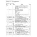
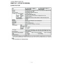
7. MENU Operation [MENU BUTTON]
8. OSD Display [ON SCREEN DISPLAY]
9. Start Mode [INPUT MODE START]
10.Mode Fixed [INPUT MODE FIXED]
[9] SOFTWARE UPDATING
1. The upgrade method of monitor software
1. The software of this machine is roughly divided into the following three software.
1) Main microcomputer software
2) Monitor microcomputer software
3) LED microcomputer software
The above-mentioned microcomputer software can rewrite software by using the USB memory to have confirmed the operation.
2. Upgrade of software
[Prior preparation]
• USB Memory
Selection
“RESPOND” or “NO RESPOND” is selectable. (Loop is provided.)
Default RESPOND
Function
Function
The MENU keys on the main unit and R/C MENU are disabled.
Exception
• Regardless of the setting contents, the start operation of the process mode, inspection mode and PUBLIC_Mode is
enabled.
• Regardless of the setting contents, all keys can be used while entering the process mode, inspection mode or
PUBLIC_Mode.
Key that becomes invalid
excluding Default besides
MENU Key because of
setting
excluding Default besides
MENU Key because of
setting
ON_TIMER, Auto Preset, Manual_Memory, and clock setting.
All Direct Shift keys to the MENU display.
All Direct Shift keys to the MENU display.
Remarks
When set to “NO RESPOND”.
• ON_TIMER is set to “OFF”.
• ON_TIMER is set to “OFF”.
Selection
“YES” or “NO” is selectable. (Loop is provided.)
Default YES
Function
Function
When set to “NO”, the following OSD is not displayed.
Register, Setting, Adjustment MENU, Channel_Call, Volume Bar In the case of Wide Model, if the following operation is
performed, it is immediately switched (since MENU can not be displayed).
Input switching.
Register, Setting, Adjustment MENU, Channel_Call, Volume Bar In the case of Wide Model, if the following operation is
performed, it is immediately switched (since MENU can not be displayed).
Input switching.
Keys which can be
enabled (Exquisite exam-
ple)
enabled (Exquisite exam-
ple)
Brightness sensor, light control.
Keys disabled when not
set to Default (Example)
set to Default (Example)
Still screen, screen display, MENU, OFF_TIMER, A V Position, Wide Mode switch, Auto Installation.
Remarks
• When set to “NO”.
a) The OFF_TIMER (SLEEP TIMER) setting time is cleared.
Selection
“NORMAL”, “TV(*Channel)”, “INPUT1”, “INPUT2” (Loop is provided.)
Default NORMAL
Function
Function
When the power is ON, the input source or channel to start is set.
In the NORMAL mode, it follows the contents of Last_Memory.
In the NORMAL mode, it follows the contents of Last_Memory.
Remarks
• When set to a mode other than “NORMAL”.
a) It is inhibited to display the Channel Setting MENU and to set the Channel.
b) On start with “ON_TIMER”, the set Channel of ON_TIMER is prior.
b) On start with “ON_TIMER”, the set Channel of ON_TIMER is prior.
• When set to “NORMAL”, “Mode Fixed (START MODE FIXED)” is set to “VARIABLE” to inhibit the selection.
When starting by "ON_TIMER", the setting Channel of ON_TIMER is priority.
When starting by "ON_TIMER", the setting Channel of ON_TIMER is priority.
Selection
“VARIABLE” or “FIXED” is selectable. (Loop is provided.)
Default VARIABLE
Function
Function
When set to “FIXED”, it is disable to switch to other channel or input after start in the set value of “Start Mode (INPUT
MODE START)”.
MODE START)”.
Keys disabled when not
set to Default (Example)
set to Default (Example)
Channel UP/Down, Direct_Channel Button, FLASHBACK, INPUT, STILL, Digit_Select and Direct input switching.
Remarks
• When “START MODE” is set to “NORMAL”, this item is disable to set. (Automatically set to “VARIABLE”.)
• When set to “FIXED”.
The Channel setting MENU (Menu-setup-Auto Installation, Programme setup and Child Lock item hatching) and Input
Selection MENU in MENU are not displayed.
• When set to “FIXED”.
The Channel setting MENU (Menu-setup-Auto Installation, Programme setup and Child Lock item hatching) and Input
Selection MENU in MENU are not displayed.
LC-52XS1E/RU/LC-65XS1E/RU
3 – 22
• PC with which Windows2000/XP/Vista was installed.
[Preparation]
When rewriting main software, it is necessary to prepare the USB memory for upgrade for beforehand.
Create the USB memory for upgrade in the following procedure.
1) The file copy of the binary image file SHOWAxxx.USB for upgrade (tentative name) is carried out at the root directory of a USB drive.
* Do not put the binary image file for a directory, a file not related, and two or more upgrades on the USB drive.
2) The USB memory for the upgrade was made above.
[How to rewrite software]
As for rewriting of software, the situation of rewriting is displayed on a display.
1) AC power supply of the main body of the monitor is turned off. (The AC outlet is pulled out.).
2) The USB memory for upgrade (what was created by the above-mentioned preparation) is inserted in the terminal for service.
3) AC power supply is turned on pushing the power button of a main part key. (AC socket is put.).
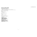
4) An upgrade screen as shown in the following figure is displayed in about 10 seconds from several seconds after main part starting.
5) When as much as one in the processing item processing fails, the upgrade failure screen is displayed as shown in the figure below. As for a failure
item, the character of "NG" changes to red.
* Do rewriting software over again when it fails and the power supply falls on the way.
When redoing, it takes about 1 minute until the screen of upgrade comes out
Even if it redoes, when failing again, hardware may be out of order.
The memory confirmed the operation is as follows.
Manufacturer:
Manufacturer:
Series name:
Part number (Representation):
Capacity
I-O DATA:
ToteBag TB-ST series:
TB-ST1G/B:
1G
Buffalo:
RUF2-S series:
RUF2-S1G-BS:
1G
Buffalo: RUF2-EL-BL
series:
RUF2-E1GL-BL:
1G
<SYSTEM UPGRADE>
PROGRAM1
90%
38%
EEPROM
OK
SHOWA
PROGRAM2
OK
NG
NG
OK
NG
PROGRAM1
EEPROM
OK
PROGRAM2
OK
NG
NG
OK
NG
<UPGRADE FAILURE>
90%
38%
SHOWA
LC-52XS1E/RU/LC-65XS1E/RU
3 – 23
6) When all processing ends, the upgrade end screen is displayed as shown in the figure below.
The version of new software can be checked on this screen.
The version display is displayed to complete the upgrade of the item of the object respectively.
Program Version: The version of main software is displayed.
7) AC power supply of a main body is turned off (AC outlet is pulled out), and the USB memory for upgrade is removed.
8) Rewriting of software is an end above.
* Check the version of the main software from 1/46 screens of the process adjustment screen by starting the set after rewriting software.
PROGRAM1
EEPROM
OK
PROGRAM2
OK
NG
NG
OK
NG
<UPGRADE SUCCESS>
Program
1.00 (W 2008/05/12 1)
System
W0805121
100%
100%
SHOWA
57%
MONITOR
OK NG
<UPGRADE SUCCESS>
SHOWA
57%
MONITOR
OK
NG
<UPGRADE FAILURE>
SHOWA
100%
MONITOR
OK
NG
<UPGRADE SUCCESS>
Monitor
1.00
SHOWA

