Sharp LC-52XD1E (serv.man6) Service Manual ▷ View online
LC-46/52XD1E-RU
7 – 21
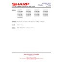
16. IC4201/4202: RH-IXB742WJZZQ
64Mb- SDRAM
17. IC4203: RH-IXB921WJZZ
16Mbit Flash Memory
Pin No.
Pin Name
I/O
Pin Function
38
CLK
I
Active on the positive going edge to sample all inputs.
19
I
Disables or enables device operation by masking or enabling all inputs except
CLK,CKE and DQM.
CLK,CKE and DQM.
37
CKE
I
Masks system clock to freeze operation from the next clock cycle.
CKE should be enabled at least one cycle prior to new command.
Disable input buffers for power down in standby.
CKE should be enabled at least one cycle prior to new command.
Disable input buffers for power down in standby.
22-26,
29-35
A0-A11
I
Row/column addresses are multiplexed on the same pins.
Row address: RA0-RA11, Column address: CA0-CA8
Row address: RA0-RA11, Column address: CA0-CA8
20, 21
BA0-BA1
I
Selects bank to be activated during row address latch time.
Selects bank for read/write during column address latch time.
Selects bank for read/write during column address latch time.
18
I
Latches row address on the positive going edge of the CLK with
low.
Eanbles row acccess <FmSdata>[amp ] precharge.
17
I
Latches column addresses on the positive going edge of the CLK with
low.
Enables column access.
16
I
Enables write operation and row precharge.
Latches data in starting from
,
active.
15,39
DQM
I/O
Makes data output Hi-Z, tsHZ after the clock and masks the output. Blocks data
input when DQM active.
input when DQM active.
2,4,5,7,8,10,11,13,42,44,45,
47,48,50,51,53
DQ0-X15
I/O
Data input/output are mutiplexed on the same pins
(X16;DQ0-15)
(X16;DQ0-15)
1,14,27,28,41,54
VDD/VSS
---
Power and ground for the input buffers and the core logic.
3,6,9,12,43,46,49,52,
VDDQ/VSSQ
---
Lsolated power supply and ground for the output buffers to provide improved
noise immunity.
noise immunity.
40
N.C/RFU
---
This pin is recommended to be left No Connection on the device.
Pin No.
Pin Name
I/O
Pin Function
1-10,
16-25,
48,13
A2-A22
I
22 Address Input.
29,31,33,35,38,40,42,44
DQ0-DQ7
I/O
8 Data Input/Output.
30,32,34,
36,39,41,43
DQ8-DQ14
I/O
Data Input/Output.
45
DQ15A-1
I/O
Data Input/Output or Address Input.
26
I
Chip Enable.
28
O
Output Enable
11
I
Write Enable.
12
I
Reset/Block Temporary Unprotect
15
O
Read/Busy Output.
47
I
Byte/Word Organization Select.
37
Vcc
-
Supply Voltage.
27,46
Vss
-
Ground.
N.C.
-
Not Connected Internally.
CS
RAS
RAS
CAS
CAS
WE
CAS WE
E
G
G
W
RP
RB
RB
BYTE
LC-46/52XD1E-RU
7 – 22
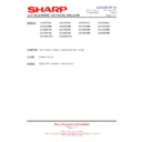
18. IC4402: VHILVC573AP-1Y
Lutch 3-State output
19. IC4401: VHITCLCX245-2Y
Interactive Balance Tranceiver
20. IC4404: VHILCX244MT-1Y
Buffer/Line Driver
Pin No.
Pin Name
I/O
Pin Function
1
I
Output Enable.
2
1D
I
Data Input 1D.
3
2D
I
Data Input 2D.
4
3D
I
Data Input 3D.
5
4D
I
Data Input 4D.
6
5D
I
Data Input 5D.
7
6D
I
Data Input 6D.
8
7D
I
Data Input 7D.
9
8D
I
Data Input 8D.
10
GND
-
Ground.
11
LE
I
Limited Enable.
12
8Q
O
Data Output 8Q.
13
7Q
O
Data Output 7Q.
14
6Q
O
Data Output 6Q.
15
5Q
O
Data Output 5Q.
16
4Q
O
Data Output 4Q.
17
3Q
O
Data Output 3Q.
18
2Q
O
Data Output 2Q.
19
1Q
O
Data Output 1Q.
20
VCC
-
Power Source.
Pin No.
Pin Name
I/O
Pin Function
1
DIR
I
Directory.
2
A1
I/O
A-Bus. Output/Input Terminal A1.
3
A2
I/O
A-Bus. Output/Input Terminal A2.
4
A3
I/O
A-Bus. Output/Input Terminal A3.
5
A4
I/O
A-Bus. Output/Input Terminal A4.
6
A5
I/O
A-Bus. Output/Input Terminal A5.
7
A6
I/O
A-Bus. Output/Input Terminal A6.
8
A7
I/O
A-Bus. Output/Input Terminal A7.
9
A8
I/O
A-Bus. Output/Input Terminal A8.
10
GND
-
Ground A9
11
B8
I/O
B-Bus Input/Output Terminal B8.
12
B7
I/O
B-Bus Input/Output Terminal B7.
13
B6
I/O
B-Bus Input/Output Terminal B6.
14
B5
I/O
B-Bus Input/Output Terminal B5
15
B4
I/O
B-Bus Input/Output Terminal B4
16
B3
I/O
B-Bus Input/Output Terminal B3
17
B2
I/O
B-Bus Input/Output Terminal B2
18
B1
I/O
B-Bus Input/Output Terminal B1
19
I
Output enable.
20
VCC
-
Power Source.
Pin No.
Pin Name
I/O
Pin Function
1, 19
OE1,OE2
I
3-STATE Output Enable Input 1 and 2
2, 4, 6, 8, 11, 13, 15, 17
I0-I7
I
Data Inputs 0-7
9, 7, 5, 3, 12, 14, 16, 18
O0-O7
O
Data Outputs 0-7
10
GND
-
Ground.
20
VCC
-
Power Source.
OE
OE
LC-46/52XD1E-RU
7 – 23
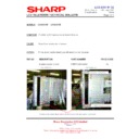
21. IC4604: VHITSH73CPT-1Y
*3-OP-AMP
Pin No.
Pin Name
I/O
Pin Function
1
I
Standby Input Terminal1.
2
I
Standby Input Terminal2.
3
I
Standby Input Terminal3.
4
VCC -
Power
Source.
5
+IN1
I
Non Inverting Input1.
6
-IN1
I
Invreting Input1.
7
OUT1
O
Output1.
8
OUT2
O
Output2.
9
-IN2
I
Inverting Input2.
10
+IN2
I
Non Inverting Input2.
11
VCC
-
Power Source.
12
+IN3
I
Non Inverting Input3.
13
-IN3
I
Inverting Input3.
14
OUT3
O
Out put3.
STB1
STB2
STB3
STB2
STB3
LC-46/52XD1E-RU
7 – 24
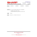
22. IC202: RH-IXB682WJZZQ
CDFDM DEMODURATOR
Pin No.
Pin Name
I/O
Pin Function
12
I
Hardware reset,active low.
62
XTALI
I
Crystal oscillator input/external clock(1.8V).
63
XTALO
O
Crystal oscillator output.
61
VCCXTAL1.8
-
Analog oscillator supply(1.8V)
64
GNDXTAL
-
Analog oscilltor ground.
2
DVCCA1.8
-
Analog part digital supply(1.8V)
5
REFM
I
Internal negative reference.
6
REFP
I
Internal positive reference.
3
VCCA1.8
-
Analog supply(1.8V).
9
INM
I
Negative analog input.
10
INP
I
Positive analog input.
4,11
GNDA
-
Analog ground.
1
DGNDA
-
Analog ground.
7
VR
I
Reference.
8
VCCA3.3
-
Analog supply(3.3V)
21
SDA
I/O
Serial data(open drain)
20
SCL
I
Serial clock(open drain)
19
SDAT
I/O
SDA tuner(open drain)
18
SCLT
I
25,26,27,29,31,32,33,34
D7/0
O
Serial D7,MPEG data.
36
CLK_OUT
O
MPEG byte or bit clock.
23
STR_OUT
O
MPEG first byte sync.
38
O
MPEG data valid/parity.
40
ERROR
O
MPEG packet error.
51
HFECO
O
Hierarchical FEC output bit 0.
50
CCLK/HFC1
O
Hierarchical FEC output bit 1 or clock for constellation display.
49
CDATA/HFC2
O
Hierarchical FEC output bit 2 or data for constellation display.
48
CIQ/HFEC3
O
Hierarchical FEC output bit 3 or IQ validation for constellation display.
16
AGC1
I/O
RF AGC control
14
AGC2
I/O
IF AGC control
17,60
TEST
-
Reserved test mode,must be ground.
58
IP0
I
General-purpose input port0 and ADC input for RF level monitoring
45
OP0
I/O
General-purpose output port0
43
LOCK/OP1
I/O
General-purpose output port1 or lock indicator.
42
LOCK/OP2
O
general-purpose output port2 or lock indicator.
47
AUX_CLK
I/O
Auxiliary clock.
55
CS0
I
Chip select LSB.
53
CS1
I
Chip select MSB.
13,28,39,57
VDD
-
Digital core supply.
22,35,44,52
VDD_3.3
-
Digital IO supply.
15,24,30,37,41,46,54,56,59
GND
-
1. All input are 3.3V compatible
2. All bidirectional pads 3.3V capable
3. All output are 3.3V capable.
2. All bidirectional pads 3.3V capable
3. All output are 3.3V capable.
RESET
D/P

