Sharp MX-FNX10 (serv.man38) Service Manual / Technical Bulletin ▷ View online
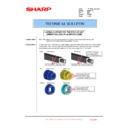
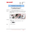
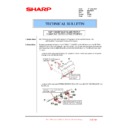
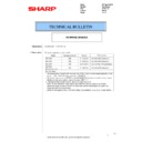
16. Raise the gears of the joint metal plate and the saddle stitch STP to separate them from the joint gears.
*You can adjust the phase without removing the metal plate by moving the gears upward as above.
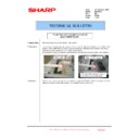
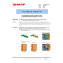
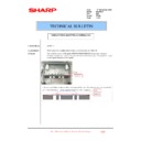
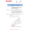
17. Move the gripper unit to the front side while the joint gear is kept apart.
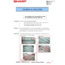
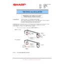
Place the gripper unit against the metal plate as indicated by the box in the picture below.
Open the gripper before moving the gripper unit by turning the square shaft shown in the picbure below
clockwise with a flat screwdriver.
(If you move it without opening the gripper, it may hit the U-shaped metal plate.
Open the gripper before moving the gripper unit by turning the square shaft shown in the picbure below
clockwise with a flat screwdriver.
(If you move it without opening the gripper, it may hit the U-shaped metal plate.
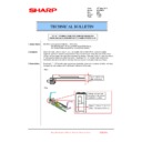
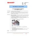
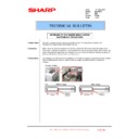
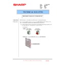
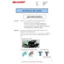
18. Move the saddle stitch STP to the front side while the joint gear is kept apart.
Move the side stitch STP to the position adjacent to the metal plate as shown by the box in the picture below.
It may be pushed back from the metal plate by the spring, but keep it in the state it touches the front side, lower
the gear of the side stitch STP turning it counterclockwise, and engage it with the joint gear.
It may be pushed back from the metal plate by the spring, but keep it in the state it touches the front side, lower
the gear of the side stitch STP turning it counterclockwise, and engage it with the joint gear.
Sharp Electronics (UK) Ltd., Technical Services Group
CCE-621
19. Attach the joint metal plate, 2 clips, and 2 screws removed in the procedures 14 and 15.
(Make sure not to drop the clips using long-nose pliers and so on.)
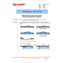
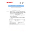
20. Check phase deviation of the semicircular gear sensor which is in the gripper unit on the rear side.
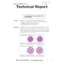
(1) Please confirm that the semicircular side of the semicircular gear faces toward the tray side.
(2) Confirm if the center of the 2 slits of the semicircular gear is at the center of the sensor.
(Confirm if the slits and the side of the sensor are parallel.)
Please adjust according to the items 21 - 22 if the phase deviates.
(2) Confirm if the center of the 2 slits of the semicircular gear is at the center of the sensor.
(Confirm if the slits and the side of the sensor are parallel.)
Please adjust according to the items 21 - 22 if the phase deviates.
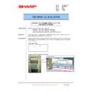
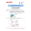
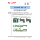
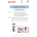
21. Remove the clip indicated by the circle in the picture below.
(Please use long-nose pliers and so on when you remove the clip so that you will not drop it.)
Sharp Electronics (UK) Ltd., Technical Services Group
CCE-621
22. Raise the semicircular gear a little and turn the gear so that the center of the 2 slits of the semicircular gear
comes to the center of the sensor on the rear side.
(Please make sure that the semicircular side of the semicircular gear faces toward the tray side.)
(Please make the slits and the sides of the sensor parallel.)
(Please be careful not to drop the semicircular gear.)
(Please make the slits and the sides of the sensor parallel.)
(Please be careful not to drop the semicircular gear.)
23. When the adjustment is finished, lower the semicircular gear to engage it with the white gear, and attach the clip.
(Please be careful not to drop the clip using long-nose pliers and so on.)
24. Attach the harness duct removed in the procedure 13, and attach the connector.
25. Return the Cover-TR-Wall and the exterior.
Note 1
Please be careful when you return the Cover-TR-Wall, because there are parts for attachment (2 parts at the
backside bottom and 3 parts at the top), to make sure it is attached correctly without a gap.
backside bottom and 3 parts at the top), to make sure it is attached correctly without a gap.
Sharp Electronics (UK) Ltd., Technical Services Group
CCE-621
Note 2
When you return the Cover-TR-Wall, pay attention to the route of the harness. Fix the harness tightly with the
clamp so that it does not interfere with the belt.
clamp so that it does not interfere with the belt.
Note 3
When you attach the rear cover, pay attention to the wiring of the interface cable, and make sure it is not
twisted or become loose. If it is twisted or loose, the cover may not be attached correctly.
twisted or become loose. If it is twisted or loose, the cover may not be attached correctly.
Note 4
Attach the right screw types according to the instruction. (It is described in the procedure for removing them.)
This is the end of confirmation and correction of phase deviation.
Sharp Electronics (UK) Ltd., Technical Services Group
CCE-621

