Sharp MX-4110N / MX-4111N / MX-4112N / MX-4110FN / MX-4111FN / MX-5110N / MX-5111N / MX-5112N / MX-5110FN / MX-5111FN (serv.man11) Service Manual ▷ View online
MX-5111N ADJUSTMENTS AND SETTINGS 4 – 92
17-B
Scan image magnification ratio adjustment
(sub scanning direction) (Manual
adjustment) (Document table mode)
(sub scanning direction) (Manual
adjustment) (Document table mode)
This adjustment must be performed in the following cases:
* When the copy magnification ratio in the copy image sub scan-
* When the copy magnification ratio in the copy image sub scan-
ning direction is not properly adjusted.
* When the scanner motor is replaced.
* U2 trouble has occurred.
* When the scanner control PWB is replaced.
* When the EEPROM of the scanner control PWB is replaced.
1)
* U2 trouble has occurred.
* When the scanner control PWB is replaced.
* When the EEPROM of the scanner control PWB is replaced.
1)
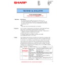
Place a scale on the document table as shown in the figure
below.
below.
2)
Enter the SIM 48-1 mode.
3)
Make a normal copy and obtain the copy magnification ratio.
Go to the copy mode, and make a copy.
Go to the copy mode, and make a copy.
4)
Check that the copy magnification ratio is within the specified
range (100
range (100
1.0%).
If the copy magnification ratio is within the specified range (100
1.0%), the adjustment is completed. If the copy magnification
ratio is not within the specified range, perform the following
procedure.
1.0%), the adjustment is completed. If the copy magnification
ratio is not within the specified range, perform the following
procedure.
5)
Change the CCD (SUB) adjustment value of Simulation 48-1.
When the adjustment value is increased, the copy magnifica-
tion ratio in the sub scanning direction is increased.
When the adjustment value is changed by 1, the copy magnifi-
cation ratio is changed by about 0.1%.
When the adjustment value is increased, the copy magnifica-
tion ratio in the sub scanning direction is increased.
When the adjustment value is changed by 1, the copy magnifi-
cation ratio is changed by about 0.1%.
Repeat the procedures 3) - 5) until the copy magnification ratio is
within the specified range (100
within the specified range (100
1.0%).
17-C
Scan image magnification ratio adjustment
(main scanning direction)
(Manual adjustment) (DSPF/RSPF mode)
(main scanning direction)
(Manual adjustment) (DSPF/RSPF mode)
This adjustment must be performed in the following cases:
* When the scan control PWB is replaced.
* When the EEPROM on the scan control PWB is replaced.
* When U2 trouble occurs.
* When the copy magnification ratio of the DSPF/RSPF mode
* When the scan control PWB is replaced.
* When the EEPROM on the scan control PWB is replaced.
* When U2 trouble occurs.
* When the copy magnification ratio of the DSPF/RSPF mode
copy image in the main scanning direction is not proper.
* When the DSPF/RSPF is disassembled.
a. Adjustment procedures
1)
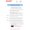
Place the duplex adjustment chart shown below on the docu-
ment tray of the DSPF/RSPF.
The adjustment chart is prepared by the following procedures.
Use A4 (11" x 8.5") paper, and put marks on both sides and
both surfaces of the paper at 10mm from each edge.
ment tray of the DSPF/RSPF.
The adjustment chart is prepared by the following procedures.
Use A4 (11" x 8.5") paper, and put marks on both sides and
both surfaces of the paper at 10mm from each edge.
2)
Make a duplex copy at the normal ratio on A4 paper.
3)
Measure the images on the copy paper and the original
images.
images.
ǂǂǂ6,08/$7,21ǂǂ12
&/26(
7(67
0$*1,),&$7,21$'-8670(17
$˖
˷̚˹
˖&&'0$,1
$˖
˖&&'68%
%˖
˖63)0$,1
&˖
˖63)68%
'˖
˖63)%0$,1
(˖
˖63)%68%
)˖
2.
10
20
90
100
110
10
20
90
100
110
10
20
90
100
110
(Example 1)
Copy A
(Shorter than
the original)
Copy A
(Shorter than
the original)
(Example 2)
Copy B
(Longer than
the original)
Copy B
(Longer than
the original)
Scale
(Original)
(Original)
Copy magnifi-
cation ratio
cation ratio
(Original dimension - Copy dimension)
Original dimension
100%
A4 size
(Both the front surface
and the back surface)
10mm
10mm
Paper pass direction
original
10
50
100
150
200
250
copy
10
50
100
150
200
250
MX-5111N ADJUSTMENTS AND SETTINGS 4 – 93
4)
Obtain the image magnification ratio according to the following
formula:
Image magnification ratio = Original size / Original size x 100
(%)
Image magnification ratio = 99 / 100 x 100 = 99 (%)
If the image magnification ratio is within the specified range
(100
formula:
Image magnification ratio = Original size / Original size x 100
(%)
Image magnification ratio = 99 / 100 x 100 = 99 (%)
If the image magnification ratio is within the specified range
(100
0.8%), there is no need to perform the adjustment.
If it is not within the specified range, perform the following pro-
cedures.
cedures.
5)
Enter the SIM 48-1 mode.
DSPF
RSPF
6)
Select an adjustment item of SPF (MAIN)/SPFB (MAIN) with
the scroll key.
the scroll key.
7)
Enter an adjustment value with 10-key, and press [OK] key.
When the adjustment value is increased, the image magnifica-
tion ratio is increased. When the adjustment value is changed
by 1, the image magnification ratio is changed by 0.02%.
When the adjustment value is increased, the image magnifica-
tion ratio is increased. When the adjustment value is changed
by 1, the image magnification ratio is changed by 0.02%.
8)
Make a normal copy and obtain the copy magnification ratio.
Repeat the procedures of 1) - 8) until a satisfactory result is
obtained.
obtained.
17-D
Scan image magnification ratio adjustment
(sub scanning direction)
(Manual adjustment) (DSPF/RSPF mode)
(sub scanning direction)
(Manual adjustment) (DSPF/RSPF mode)
This adjustment must be performed in the following cases:
* When the SCAN CONTROL PWB is replaced.
* When the EEPROM on the SCAN CONTROL PWB is replaced.
* When U2 trouble occurs.
* When the copy magnification ratio of the DSPF/RSPF mode
* When the SCAN CONTROL PWB is replaced.
* When the EEPROM on the SCAN CONTROL PWB is replaced.
* When U2 trouble occurs.
* When the copy magnification ratio of the DSPF/RSPF mode
copy image in the sub scanning direction is not proper.
* When the DSPF/RSPF is disassembled.
1)
1)
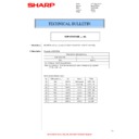
Place the duplex adjustment chart shown below on the docu-
ment tray.
The adjustment chart is prepared by the following procedures.
Use A4 (11" x 8.5") paper, and put marks on both sides and
both surfaces of the paper at 10mm from each edge.
ment tray.
The adjustment chart is prepared by the following procedures.
Use A4 (11" x 8.5") paper, and put marks on both sides and
both surfaces of the paper at 10mm from each edge.
2)
Make a duplex copy at the normal ratio on A4 paper.
3)
Measure the images on the copy paper and the original
images.
images.
4)
Obtain the image magnification ratio according to the following
formula:
Image magnification ratio = Original size / Original size x 100
(%)
Image magnification ratio = 99 / 100 x 100 = 99 (%)
If the image magnification ratio is within the specified range
(100
formula:
Image magnification ratio = Original size / Original size x 100
(%)
Image magnification ratio = 99 / 100 x 100 = 99 (%)
If the image magnification ratio is within the specified range
(100
0.8%), there is no need to perform the adjustment.
If it is not within the specified range, perform the following pro-
cedures.
cedures.
Item
Display
Content
Setting
range
Default
value
A
CCD(MAIN)
SCAN main scanning
magnification ratio
adjustment (CCD)
magnification ratio
adjustment (CCD)
1 - 99
50
B
CCD(SUB)
SCAN sub scanning
magnification ratio
adjustment (CCD)
magnification ratio
adjustment (CCD)
1 - 99
50
C
SPF(MAIN)
DSPF document front surface
magnification ratio
adjustment (Main scan)
magnification ratio
adjustment (Main scan)
1 - 99
50
D
SPF(SUB)
DSPF document front surface
magnification ratio
adjustment (Sub scan)
magnification ratio
adjustment (Sub scan)
1 - 99
50
E
SPFB(MAIN)
DSPF document back
surface magnification ratio
adjustment (Main scan)
surface magnification ratio
adjustment (Main scan)
1 - 99
50
Item
Display
Content
Setting
range
Default
value
A
CCD(MAIN)
SCAN main scanning
magnification ratio
adjustment (CCD)
magnification ratio
adjustment (CCD)
1 - 99
50
B
CCD(SUB)
SCAN sub scanning
magnification ratio
adjustment (CCD)
magnification ratio
adjustment (CCD)
1 - 99
50
C
SPF(MAIN)
RSPF document front surface
magnification ratio
adjustment (Main scan)
magnification ratio
adjustment (Main scan)
1 - 99
50
D
SPF(SUB)
RSPF document front surface
magnification ratio
adjustment (Sub scan)
magnification ratio
adjustment (Sub scan)
1 - 99
50
E
SPFB(MAIN)
RSPF document back
surface magnification ratio
adjustment (Main scan)
surface magnification ratio
adjustment (Main scan)
1 - 99
50
F
SPFB(SUB)
RSPF document back
surface magnification ratio
adjustment (Sub scan)
surface magnification ratio
adjustment (Sub scan)
1 - 99
50
SPF (MAIN)
Main scanning direction image magnification ratio
(Front surface)
(Front surface)
SPFB (MAIN) Main scanning direction image magnification ratio
(Back surface)
ǂǂǂ6,08/$7,21ǂǂ12
&/26(
7(67
0$*1,),&$7,21$'-8670(17
$˖
˷̚˹
˖&&'0$,1
$˖
˖&&'68%
%˖
˖63)0$,1
&˖
˖63)68%
'˖
˖63)%0$,1
(˖
˖63)%68%
)˖
2.
A4 size
10mm
10mm
Paper pass direction
original
copy
10
50
100
150
200
10
50
100
150
200
MX-5111N ADJUSTMENTS AND SETTINGS 4 – 94
5)
Enter the SIM 48-1 mode.
6)
Select an adjustment item with the scroll key.
7)
Enter an image magnification ratio adjustment value with 10-
key, and press [OK] key.
When the adjustment value is increased, the image magnifica-
tion ratio is increased.
When the adjustment value is changed by 1, the image magni-
fication ratio is changed by 0.1%.
key, and press [OK] key.
When the adjustment value is increased, the image magnifica-
tion ratio is increased.
When the adjustment value is changed by 1, the image magni-
fication ratio is changed by 0.1%.
8)
Make a normal copy and obtain the copy magnification ratio.
Repeat the procedures of 1) - 8) until a satisfactory result is
obtained.
obtained.
ADJ 18
Scan image off-center
adjustment
(Manual adjustment)
adjustment
(Manual adjustment)
NOTE:
Normally if the adjustment is executed by ADJ 4 (automatic adjust-
ment), there is no need to execute this adjustment.
Only when the manual adjustment is required, execute this adjust-
ment.
In other words, this manual adjustment is executed when a satis-
factory result is not obtained from the automatic adjustment (ADJ
4).
18-A
Scan image off-center adjustment (Manual
adjustment) (Document table mode)
adjustment) (Document table mode)
This adjustment must be performed in the following cases:
* When the scanner (reading) section is disassembled.
* When the scanner (reading) unit is replaced.
* When a U2 trouble occurs.
* When the scanner control PWB is replaced.
* When the EEPROM on the scanner control PWB is replaced.
1)
* When the scanner (reading) section is disassembled.
* When the scanner (reading) unit is replaced.
* When a U2 trouble occurs.
* When the scanner control PWB is replaced.
* When the EEPROM on the scanner control PWB is replaced.
1)
Make a copy of the adjustment chart (made by yourself) in the
adjustment mode (document table).
adjustment mode (document table).
2)
Check the copy image center position.
If A - B =
If A - B =
1.0mm, the adjustment is not required.
If the above condition is not satisfied, perform the following
procedures.
procedures.
3)
Enter the SIM 50-12 mode.
4)
Select the adjustment mode OC with the scroll key.
5)
Enter the adjustment value with 10-key, and press [OK] key.
The entered value is set.
When the set value is increased, the main scanning print posi-
tion is shifted to the front side by 0.1mm.
The entered value is set.
When the set value is increased, the main scanning print posi-
tion is shifted to the front side by 0.1mm.
6)
Go to the copy mode, and make a copy.
Repeat the procedures of 1) - 6) until the above condition is satis-
fied.
fied.
18-B
Scan image off-center adjustment
(Manual adjustment) (DSPF/RSPF mode)
(Manual adjustment) (DSPF/RSPF mode)
This adjustment must be performed in the following cases:
* When the scan control PWB is replaced.
* When the EEPROM on the scan control PWB is replaced.
* When the scanner (reading) section is disassembled.
* When the scanner (reading) section is replaced.
* When U2 trouble occurs.
* When the DSPF/RSPF section is disassembled.
* When the DSPF/RSPF unit is replaced.
NOTE: To execute this adjustment, it is required that the ADJ 18A
Scan image off-center adjustment (Document table mode)
must have been properly adjusted.
must have been properly adjusted.
SPF (SUB)
Sub scanning direction image magnification ratio
(Front surface)
(Front surface)
SPFB (SUB)
Sub scanning direction image magnification ratio
(Back surface)
(Back surface)
B
A = B
A
B'
A' - B' =
1.0mm
A'
(100%)
ǂǂǂ6,08/$7,21ǂǂ12
&/26(
7(67
25,*,1$/&(17(52))6(76(783
$˖
˷̚˹
˖2&
$˖
˖63)6,'(
%˖
˖63)6,'(
&˖
2.
MX-5111N ADJUSTMENTS AND SETTINGS 4 – 95
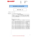
1)
Prepare the adjustment chart.
Draw a line at the center of the front surface and the back sur-
face of A4 (11" x 8.5") paper in parallel with the paper transport
direction.
Draw a line at the center of the front surface and the back sur-
face of A4 (11" x 8.5") paper in parallel with the paper transport
direction.
2)
Set the adjustment chart to the RSPF.
3)
Make a duplex copy in the normal magnification ratio from the
manual paper feed tray, and check the image position on the
front surface and the back surface of the copy paper.
manual paper feed tray, and check the image position on the
front surface and the back surface of the copy paper.
If the difference is within the range of 0
2.7mmm there is no
need to perform the adjustment.
If the adjustment is required, perform the following procedures.
If the adjustment is required, perform the following procedures.
4)
Enter the SIM 50-12 or 50-6 mode.
SIM50-12
A - C: When the adjustment value is increased, the image
position is shifted to the rear frame side.
1step = 0.1mm
SIM50-6
position is shifted to the rear frame side.
1step = 0.1mm
SIM50-6
DSPF
Paper transport direction
Front surface
Back surface
Draw a line at the center of the
front surface and the back surface
of paper in parallel with the paper
transport direction.
original
copy
a
b
ǂǂǂ6,08/$7,21ǂǂ12
&/26(
7(67
25,*,1$/&(17(52))6(76(783
$˖
˷̚
˹
˖2&
$˖
˖63)
6,'(
%˖
˖63)
6,'(
&˖
2.
(SIM50-12)
Item
Display
Content
Setting
range
Default
value
A
OC
Document table image off-
center adjustment
center adjustment
1 - 99
50
B
SPF(SIDE1)
SPF front surface image off-
center adjustment
center adjustment
1 - 99
50
C
SPF(SIDE2)
SPF back surface image off-
center adjustment
center adjustment
1 - 99
50
Item/Display
Content
Setting
range
Default
value
A
SIDE1
Front surface
document scan
position adjustment
(CCD)
document scan
position adjustment
(CCD)
1 - 99
50
B
SIDE2
Back surface
document scan
position adjustment
(CCD)
document scan
position adjustment
(CCD)
1 - 99
50
C
Image loss
amount
setting
SIDE1
amount
setting
SIDE1
LEAD_
EDGE
(SIDE1)
EDGE
(SIDE1)
Front surface lead
edge image loss
amount setting
edge image loss
amount setting
0 - 99
20
D
FRONT_
REAR
(SIDE1)
REAR
(SIDE1)
Front surface side
image loss amount
setting
image loss amount
setting
0 - 99
20
E
TRAIL_
EDGE
(SIDE1)
EDGE
(SIDE1)
Front surface rear
edge image loss
amount setting
edge image loss
amount setting
0 - 99
40
F
Image loss
amount
setting
SIDE2
amount
setting
SIDE2
LEAD_
EDGE
(SIDE2)
EDGE
(SIDE2)
Back surface lead
edge image loss
amount setting
edge image loss
amount setting
0 - 99
40
G
FRONT_
REAR
(SIDE2)
REAR
(SIDE2)
Back surface side
image loss amount
setting
image loss amount
setting
0 - 99
20
H
TRAIL_
EDGE
(SIDE2)
EDGE
(SIDE2)
Back surface rear edge
image loss amount
setting
image loss amount
setting
0 - 99
20
I
OFFSET_SPF1
DSPF front surface
document off-center
adjustment
document off-center
adjustment
1 - 99
50
J
OFFSET_SPF2
DSPF back surface
document off-center
adjustment
document off-center
adjustment
1 - 99
50
K
SCAN_SPEED_SPF1
DSPF document front
surface magnification
ratio (Sub scan)
surface magnification
ratio (Sub scan)
1 - 99
50
ǂǂǂ6,08/$7,21ǂǂ12
&/26(
7(67
/($'('*($'-8670(179$/8(
63)
$˖
˷̚
˹
˖6,'(
$˖
˖6,'(
%˖
˖/($'B('*(
6,'(
&˖
˖)5217B5($5
6,'(
'˖
˖/($'B('*(
6,'(
)˖
˖75$,/B('*(
6,'(
(˖
˖)5217B5($5
6,'(
*˖
˖75$,/B('*(
6,'(
+˖
˖2))6(7B63)
,˖
˖2))6(7B63)
-˖
˖6&$1B63(('B63)
.˖
2.
(SIM50-6)

