Sharp AR-F14 (serv.man5) Service Manual ▷ View online
AR-F14/PN1 DISASSEMBLY AND ASSEMBLY 5-17
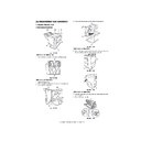
2. Puncher Unit (option)
A.Puncher Driving System
(1)Removing the Punch Motor
1) Remove the two screws [1].
2) Disconnect the connector [2] to remove the punch motor [3].
Fig.F03-201-01
(2)Removing the Horizontal Registration Motor
1) Disconnect connector [1].
2) Remove the harness [3] from the harness guide [2].
3) Remove the two screws [4] to remove the horizontal registration
3) Remove the two screws [4] to remove the horizontal registration
motor [5].
Fig.F03-201-02
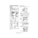
(3)Removing the Punch Unit
1) Remove the waste case.
2) Remove the screw [1] to detach the jam processing cover [2].
Fig.F03-201-03
3) Disconnect the connector [3]
4) Remove the harness [5] from the harness guide [4].
4) Remove the harness [5] from the harness guide [4].
Fig.F03-201-04
5) Disconnect the connector [6].
6) Remove the screw [7] and sensor support plate [8].
Fig.F03-201-05
7) Remove the screw [9] and washer [10].
8) Disconnect the connector [11].
9) Remove the two screws [12] to detach the base cover [13].
Fig.F03-201-06
[2]
[1]
[3]
[4]
[5]
[2]
[1]
[3]
[2]
[1]
[3]
[5]
[4]
[6]
[7]
[8]
[13]
[9]
[10]
[12]
[11]
[05]DISASSEMBLYANDASSEMBLY.fm 17 ページ 2004年4月19日 月曜日 午後1時38分
AR-F14/PN1 DISASSEMBLY AND ASSEMBLY 5-18
10)Remove the four screws [14] to remove the upper transmission
sensor unit [15] and lower transmission sensor [16].
Fig.F03-201-07
11) Remove the punch unit [18] from the horizontal registration motor
assembly [17].
Fig.F03-201-08
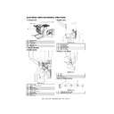
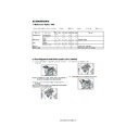
B. PCBs
(1)Removing the Punch Controller PCB
1) Remove the two screws [1].
2) Disconnect the five connectors [2] to remove the punch controller
2) Disconnect the five connectors [2] to remove the punch controller
PCB [3].
Fig.F03-202-01
(2)Removing the Photosensor PCB
1) Remove the punch motor. (See 2.A.(1).)
2) Remove the screw [1].
2) Remove the screw [1].
3) Remove the harness [3] from the harness guide [2] on the PCB, then
detach the PCB cover [4].
Fig.F03-202-02
4) Disconnect the connector [5] to remove the photosensor PCB [6].
Fig.F03-202-03
[14]
[14]
[14]
[15]
[16]
[17]
[18]
[2]
[3]
[2]
[2]
[1]
[4]
[1]
[2]
[3]
[6]
[5]
[05]DISASSEMBLYANDASSEMBLY.fm 18 ページ 2004年4月19日 月曜日 午後1時38分
AR-F14/PN1 DISASSEMBLY AND ASSEMBLY 5-19
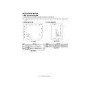
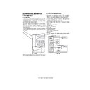
(3)Removing the LED PCB
1) Remove the waste case.
2) Disconnect connector [1].
3) Remove the harness [3] from the harness guide [2].
3) Remove the harness [3] from the harness guide [2].
Fig.F03-202-04
4) Remove the screw [4] and washer [5].
5) Disconnect the connector [6].
6) Remove the screw [7] to detach the base cover [8].
6) Remove the screw [7] to detach the base cover [8].
Fig.F03-202-05
7) Remove the screw [9].
8) Disconnect the connector [10] to remove the LED PCB [11].
Fig.F03-202-06
(4)Removing the Waste-Full Photosensor PCB
1) Remove the punch controller PCB. (See 2.B.(1).)
2) Remove the two screws [1] to remove the PCB film [2].
Fig.F03-202-07
3) Disconnect the connector [3] to remove the waste-full photosensor
PCB [4].
Fig.F03-202-08
(5)Removing the Waste Full LED PCB
1) Remove the screw [1].
2) Disconnect the connector [2] to remove the waste-full LED PCB [3].
Fig.F03-202-09
[1]
[3]
[2]
[8]
[4]
[5]
[7]
[6]
[11]
[10]
[9]
[2]
[1]
[4]
[3]
[2]
[1]
[3]
[05]DISASSEMBLYANDASSEMBLY.fm 19 ページ 2004年4月19日 月曜日 午後1時38分

