Sharp AR-C270 (serv.man15) Service Manual ▷ View online
(AR-C160/C270)
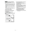
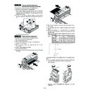
1) Remove the operation unit.
Left side Right side
2) Remove the left and right upper cabinet.
3) Remove the ICU PWB shield plate.
4) Remove the CCD flat cable connector.
5) Open the scanner (reading) unit and fix it with the hold shaft.
6)
Remove the screw, and remove the ICU cover.
7)
Remove the ICU main PWB, the ICU image PWB, and the ICU
scan PWB.
scan PWB.
11 – 33
S10/P04
PCU main PWB (AR-C250/C160/C270)
S10/P04
PCU main PWB A (AR-C100/C150)
S10/P05
PCU main PWB B (AR-C100/C150)
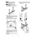
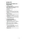
1) Remove the rear cabinet upper. S01/P02
2) Remove the rear cabinet lower. S01/P03
3) Remove the screw and the connector, and remove the PCU main
PWB A and the PCU main PWB B.
(AR-C100/C150)
(AR-C160/C270)
S10/P06
PCU sub PWB
1) Remove the transfer cover and the fusing cover. S06/Ua06
2) Remove the PCU sub PWB.
S10/P07
Scanner lamp control PWB
1) Remove the rear cabinet upper. S01/P02
2) Remove the rear cabinet lower. S01/P03
3) Remove the screw and the connector, and remove the scanner
lamp control PWB.
S10/P04
11 – 34
S10/P08
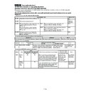
AC main power PWB
1) Remove the rear cabinet upper. S01/P02
2) Remove the rear cabinet lower. S01/P03
3) Remove the screw and the connector, and remove the AC main
power PWB.
Remove it from the notch section (#1) of the frame.
S10/P09
DC main power PWB
(AR-C100/C150/C250)
(AR-C100/C150/C250)
S10/P09
DC power PWB (AR-C160/C270)
1) Remove the rear cabinet upper. S01/P02
2) Remove the rear cabinet lower. S01/P03
3) Remove the screw and the connector, and remove the AC power
unit.
4) Remove the screw and the connector, and remove the DC main
power PWB. (AR-C100/C150/C250)
Remove the screw and the connector, and remove the DC power
PWB. (AR-C160/C270)
Remove if from the notch section of the chassis R side (#1).
Remove the screw and the connector, and remove the DC power
PWB. (AR-C160/C270)
Remove if from the notch section of the chassis R side (#1).
(AR-C100/C150/C250)
(AR-C160/C270)
S10/P10
DC sub power PWB (AR-C100/C150/C250)
S10/P10
Power control PWB (AR-C160/C270)
1) Remove the rear cabinet upper. S01/P02
2) Remove the rear cabinet lower. S01/P03
3) Remove the screw and the connector, and remove the DC sub
power PWB. (AR-C100/C150/C250)
Remove the screw and the connector, and remove the power con-
trol PWB. (AR-C160/C270)
Remove the screw and the connector, and remove the power con-
trol PWB. (AR-C160/C270)
(AR-C100/C150/C250)
#1
S10/P08
S10/P09
S10/P10
11 – 35
(AR-C160/C270)
S10/P11
OPC drum drive PWB
(AR-C100/C150/C250)
(AR-C100/C150/C250)
S10/P11
OPC drum drive/Signal interface PWB
(AR-C160/C270)
(AR-C160/C270)
1) Remove the rear cabinet upper. (S01/P02)
2) Remove the rear cabinet lower. (S01/P03)
3) Remove the connector, and remove the OPC drum drive PWB.
2) Remove the rear cabinet lower. (S01/P03)
3) Remove the connector, and remove the OPC drum drive PWB.
(AR-C100/C150/C250)
Remove the connector, and remove the OPC drum drive/Signal
interface PWB. (AR-C160/C270)
Remove the connector, and remove the OPC drum drive/Signal
interface PWB. (AR-C160/C270)
Remove if from the notch section of the frame (#1). When assem-
bling, engage it with the notch section.
(AR-C100/C150/C250)
bling, engage it with the notch section.
(AR-C100/C150/C250)
(AR-C160/C270)
S10/P12
High voltage power interface PWB
1) Remove the rear cabinet upper. S01/P02
2) Remove the rear cabinet lower. S01/P03
3) Remove the screw and the connector, and remove the high volt-
age power interface PWB.
Slide the MC brunch PWB (#1) to the left to remove it from the high
voltage PWB mounting plate.
voltage PWB mounting plate.
S10/P13
High voltage power PWB (Main charger/
Developing bias)
Developing bias)
1) Remove the rear cabinet upper. S01/P02
2) Remove the rear cabinet lower. S01/P03
3) Remove the screw and the connector, and remove the high volt-
age power PWB (main charger. Developing bias).
S10/P14
High voltage power PWB (Transfer
charger)
charger)
1) Remove the transfer inner unit. S06/Ua06
2) Remove the high voltage power PWB (transfer charger).
S10/P10
S10/P11
11 – 36

