Sharp AR-C270 (serv.man12) Service Manual ▷ View online
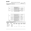
ADJ M21
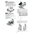
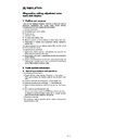
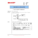
Transfer belt level adjustment
(Transfer belt traveling adjustment)
(Transfer belt traveling adjustment)
This adjustment must be performed in the following cases:
•
When the transfer belt section is disassembled.
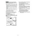
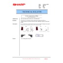
1) Make a copy of gray half tone on the whole surface, and check for
a color balance difference between the front and the rear sides.
Check that there is no difference in the color balance of the front
side and the rear side.
Check that there is no difference in the color balance of the front
side and the rear side.
2) If there is a color balance difference between the front and the
rear sides, change the height of the level adjustment angle to ad-
just.
just.
It is fixed at the center normally.
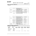
ADJ M22
Fusing pressure adjustment
This adjustment must be performed in the following cases:
•
When the fusing section is disassembled.
•
When a fusing trouble occurs.
•
When wrinkles are generated on paper in the fusing section.
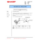
1) Select A4 (8.5
×
11) paper.
chrome copy.
3) A copy of black background is made.
4) Pull out the transfer section.
5) Insert paper into the pre-transfer paper guide, and turn the fusing
roller knob.
6) With the paper squeezed in the pre-transfer paper guide, wait for
about 10sec.
7) Turn the fusing roller knob to remove the paper from the fusing
section.
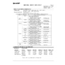
8) Measure the dimension (L) of the center section of the glittering
line made by the fusing roller. Check that the dimension is in the
specified range.
Check that the pressure balance between the front and the rear
frame sides is proper.
specified range.
Check that the pressure balance between the front and the rear
frame sides is proper.
Value L
Model
Japan
Except Japan
AR-C100
5.5 – 6.0 mm
5.5 – 6.0 mm
AR-C150
5.5 – 6.0 mm
5.5 – 6.0 mm
AR-C250
6.0 – 7.0 mm
6.5 – 7.5 mm
AR-C160/C270
6.5 – 7.5 mm
6.5 – 7.5 mm
If the above condition is not satisfied, perform the following proce-
dure.
dure.
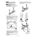
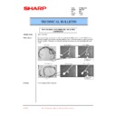
9) Turn the pressure adjustment screw on the front and the rear
frame sides of the fusing unit to adjust the fusing pressure.
(AR-C100/C150)
Adjustment wrench (UKOG-0282FCZZ) (Required for the AR-
C100/C150)
C100/C150)
LR
L (Center)
LF
LR = LF
7 – 45
(AR-C250/C160/C270)
Repeat procedures 2) – 9) until the condition of procedure 8) is satis-
fied.
fied.
ADJ M23
Power voltage adjustment
(AR-C100/C150/C250/C270)
(AR-C100/C150/C250/C270)
This adjustment must be performed in the following cases:
•
When a part in the DC power unit is replaced.
ADJ 1
3.4V power voltage adjustment
1) Put the multi-meter on the 3.4V line of the DC main PWB and
GND.
2) Turn VR704 on the DC main PWB to adjust so that the voltage is
3.4V.
ADJ 2
5.0V power voltage adjustment
1) Put the multi-meter on the 5.0V line of the DC main PWB and
GND.
2) Turn VR703 on the DC main PWB to adjust so that the voltage is
5.0V.
ADJ 3
24V power voltage adjustment
1) Put the multi-meter on the 24V line of the DC main PWB and
GND.
2) Turn VR702 on the DC main PWB to adjust so that the voltage is
24.0V.
ADJ M24
Manual paper feed size detection level
adjustment
adjustment
This adjustment must be performed in the following cases:
•
When the manual paper feed tray section is disassembled.
•
When the manual paper feed tray is replaced.
•
When a U2 trouble occurs.
•
When the PCU main PWB is replaced.
•
When the EEPROM of the PCU main PWB is replaced.
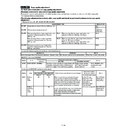
1) Execute SIM 40-2.
2) Extend the manual paper feed guide fully.
3) Press [MAX POSITION] on the LCD of the operation panel to
highlight it.
4) Press [EXECUTE] on the LCD of the operation panel to highlight
it.
If normal, the highlight is shifted from [MAX POSITION] to [MIN
POSITION].
POSITION].
5) Narrow the manual paper feed tray guide fully.
6) Press [EXECUTE] on the LCD of the operation panel to highlight
it.
Check that [COMPLETE] is highlighted.
ADJ M25
OHP sensor adjustment
This adjustment must be performed in the following cases:
•
When the OHP sensor is replaced.
•
When the OHP sensor is disassembled.
•
When a U2 trouble occurs.
•
When the PCU main PWB is replaced.
•
When the EEPROM of the PCU main PWB is replaced.
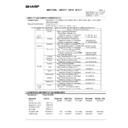
1) Enter the SIM 40-5 mode.
2) Set A4 (11
×
8.5) paper to the manual paper feed tray.
3) Press the EXECUTE key.
Paper in the manual paper feed tray is fed and stopped at the OHP
sensor section.
sensor section.
The sensor LED current level is automatically adjusted so that the
specified (target) output of the OHP sensor is supplied.
specified (target) output of the OHP sensor is supplied.
After adjustment, paper is discharged and the result data is displayed.
When the adjustment is completed normally, ADJUSTMENT COM-
PLETE is displayed. When an error occurs, ADJUSTMENT ERROR
is displayed.
PLETE is displayed. When an error occurs, ADJUSTMENT ERROR
is displayed.
7 – 46
Display

