Sharp AR-651 (serv.man4) Service Manual ▷ View online
4 - 13
AR-651/810 PREVENTIVE MAINTENANCE
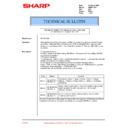
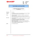
Remarks “*” in the Preventive Maintenance Check List
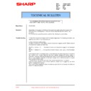
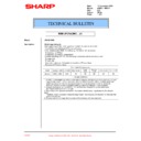
*1 Original glass
Clean both sides of the original glass.
Note: Make sure that there is no fingerprints or oil staining on part of the original glass on where the original
scale is mounted since the shading correction plate is located below the scale to be scanned.
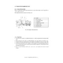
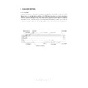
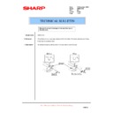
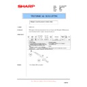
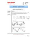
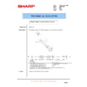
*2 Slit glass
Take off the slit glass unit and clean the face side and back side of the glass.
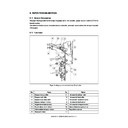
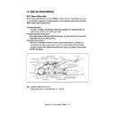
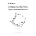
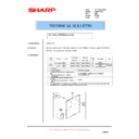
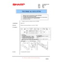
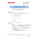
*3 Pickup roller and feed roller
When installing the pickup roller and feed roller, pay attention to allocate the pickup roller, gear, feed
roller and one-way clutch correctly.
*4 Separation roller
When replacing the separation roller, replace only the roller and continue to use the torque limitter.
(2)
(1)
Gear
Pickup roller
Idler gear
shaft
Torque
limitter
Separation roller
Feed roller
One-way
clutch
Slit glass
Face to be cleaned
AR-651/810 PREVENTIVE MAINTENANCE
4 - 14
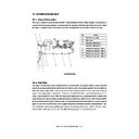
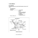
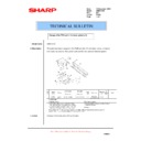
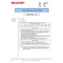
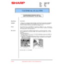
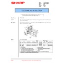
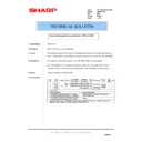
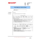
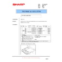
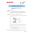
*7 Cleaner Unit / Image quality sensor / Drum shaft bearing
Be sure to connect the ground lead to the aluminum die cast on the rear of the cleaner (exit side) before
you clean the cleaner unit. Then clean the unit with, for example, a vacuum cleaner.
(If the cleaner unit is not grounded, static electricity may damage the image quality sensor.)
Also wipe the window of the image quality sensor with a cotton wool bud or tissue.
(If the window of the image quality sensor is dirty, the sensor may no longer function properly.)
*5 Drive gears in the paper feeding section (teeth face and shafts)
Apply some white molycote to the teeth faces and shafts of the drive gears.
Note: Make sure that oil is not running over or scattered around as the gear is rotated coming into the clutch
after applying molycote to the gear which is located near the clutch. The quantity of molycote should be
smaller than that to be applied to the other parts.
*6 Main charger case/main charger wire
Clean the main charger case and wire with a cloth soaked in water and squeezed tightly, and then wipe
them with a dry cloth.
Note: Be careful of the following when attaching a new wire (length: 363mm).
• Insert the wire securely into the V-grooves of the front and rear sides.
• Do not twist the wire.
• Do not touch the wire with your bare hand.
Next, wipe the inner diameter of the drum shaft
bearing with a cloth.
(If toner adheres to the inner diameter, you may
no longer be able to draw out the drum shaft.)
Image quality sensor
Connected to earth
Drum shaft
bearing
4 - 15
AR-651/810 PREVENTIVE MAINTENANCE
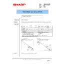
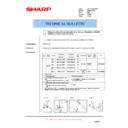
*8 Drum cleaning blade / Drum creaning brush
Since the edge of the blade is breakable and can be easily damaged by matters such as the adherence
of paper dust. Replace the cleaning blade and brush with new ones if poor images are copied due to the
damaged blade regardless of the number of copies which have been made.
*9 Recovery blade
Replace the recovery blade regardless the number of copies if the edge of the blade get damaged.
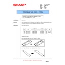
*10 Separation fingers for the drum
The paper jam may be caused if the tip of the separation finger is damaged or deformed. If there is any
problem with it, replace the finger with a new one regardless of the number of copies which have been
made.
If any mark which was made by the finger appears on the printed image, clean the tip of the finger.
Notes: 1. Wipe the tip of the finger lightly with a dry cloth trying not to deform it.
Do not leave the lint on the tip.
2. Apply patting power to the tip of the fingers and drum surface after replacing or cleaning them.
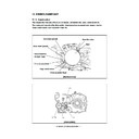
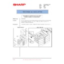
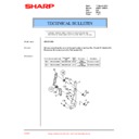
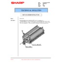
*11 Toner transport auger drive section
Apply white grease to the toner transport auger drive section (shown by arrow).
*12 Developer material
After replacing the developer material, be sure to perform the auto-toner adjustment and then enforced
performing of image quality control.
AR-651/810 PREVENTIVE MAINTENANCE
4 - 16
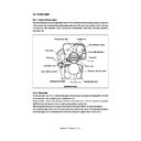
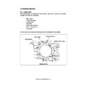
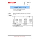
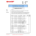
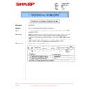
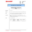
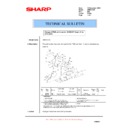
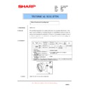
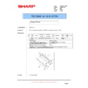
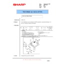
*13 Oil seal
Mixer shaft .......................... 4 pcs.
Paddle shaft ........................ 2 pcs.
Upper developer sleeve ....... 1 pc.
Lower developer sleeve ....... 1 pc.
Transport sleeve ................. 1 pc.
During replacement, coat the oil seal with grease
(Alvanian No.2).
(1) Push in a new oil seal parallel to the mounting
hole section of the developer frame or outside
of the nozzle mixer.
* Pay attention to the direction in which the
oil seal is attached. (See figure on right.)
(2) Apply an even coat of grease to the inside of
the oil seal.
• Amount: About two small drops
(3) Wipe off any grease the exudes from the inside.
Out side
Inside
Developer frame
(Nozzle mixer)
Grease
Oil seal
Mixer Shaft
Apply a coating of grease (Alvania No.2) to the
entire periphery of the mixer shaft before attaching
the bearing.
Mixer shaft
Bearing

