Sharp AR-651 (serv.man20) Service Manual ▷ View online
AR-651/810 POWER SUPPLY UNIT 17 - 5
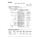
17. 4. Fuse
When the power supply secondary fuse is blown out, confirm that there is no abnormality with each part
using the following table.
Voltage
Board/Unit
Part
Fuse type
24VA
LGC
System fan motor
F3: 4A (Semi time-lag)
Duct in fan motor
Laser unit fan motor
Developer unit fan motor
Developer unit motor
Drum separation finger solenoid
Total counter
Key copy counter
Gate solenoid
Duct out fan motor
24VB
LGC
Main switch
F4: 4A (Semi time-lag)
Auto-toner sensor
Drum surface potential sensor
Discharge lamp
High-voltage developer bias
Reverse motor
Exit motor
Transfer belt cam motor
Charger wire cleaner drive motor
Used toner transport motor
Cleaning brush drive motor
New toner supply motor
Toner recycle hopper motor
24VC
LGC
Reversed paper transport clutch 1/2
F5: 4A (Semi time-lag)
1st/2nd cassette transport clutch
Tandem LCF transport clutch
1st/2nd cassette feed clutch
Tandem LCF feed clutch
Bypass feed clutch
Reversed paper transport driving clutch
Intermediate transport clutch
Bypass pickup solenoid
Tandem LCF pickup solenoid
End fence solenoid
Duct out fan motor
Exit fan motor
Reverse section fan motor 1/2
AR-651/810 POWER SUPPLY UNIT 17 - 6
Voltage
Board/Unit
Part
Fuse type
24VC
LGC
Registration motor
F5: 4A (Semi time-lag)
LCF unit
IH fan motor
Cassette tray-up motor 1/2
LCF tray-up motor
36VA
LGC
Fuser unit motor
F6: 4A (Semi time-lag)
Feed motor
36VB
LGC
Drum motor
Transfer belt motor
24VD
PLG
Polygonal motor
F7: 4A (Semi time-lag)
(OPT)
Laser unit fan motor
24VE
SLG
SLG fan motor
(Scanner)
SLG fan motor driver circuit (SLG board)
Lamp inverter
36VC
SLG
Scanner motor
F8: 4A (Semi time-lag)
(Scanner)
Scanner motor driver circuit (SLG board)
24VH
Finisher
F9: 8A (Semi time-lag)
24VF
RADF
F10: 5A (Semi time-lag)
24VG
LGC
Monitoring system
Total Counter
AR-651/810 POWER SUPPLY UNIT 17 - 7
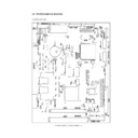
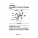
17. 5. Configuration of Power Supply Unit
F5
F6
F1
F3
F7
F8
F10
F2
Reg.
Reg.
24VA(LGC)
24VB(LGC)
24VC(LGC)
36VA(LGC)
36VB(LGC)
24VD(PLG)
24VE(SLG)
5.1VA(PLG)
36VC(SLG)
24VH(FIN)
3.3VC(SYS)
5.1VB(SYS)
12VA(SYS)
5.1VC(SYS)
5.1VD(LGC)
12VD(LGC)
24VG(LGC)
24VF(RADF)
3.3VB(SLG)
5.1VE(SLG)
12VC(SLG)
5.1VF(PLG)
5.1VG(PLG)
3.3VA(PLG)
12VB(PLG)
5.1VH(FIN)
F4
F9
Live
Neutral
Breaker
Noise
filter
filter
Main switch
Door switch
IH
Frequency
reactor
reactor
Noise
filter
filter
Switching power supply
Frequency
reactor
reactor
Noise
filter
filter
AR-651/810 POWER SUPPLY UNIT 17 - 8
ON
OFF
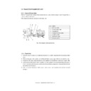
17. 6. Power Supply Sequence
AC input
+3.3V(MAIN)
+5.1V(MAIN)
PWR-DN
+12V(MAIN)
+24V(MAIN)
+5.1V(DOOR)
+24V(DOOR)
+36V(DOOR)
Within 700ms
Within 10ms
3.2V or more
4.95V or more
11.4V or more
21.6V or more
4.95V or more
21.6V or more
34.2V or more
3.2V or more
4.95V or more
11.4V or more
21.6V or more
4.95V or more
21.6V or more
34.2V or more
10ms~120ms
20ms
or
more
or
more
10ms
or
more
or
more
20ms
or
more
or
more
50ms
or
more
or
more
0~200ms
5ms or more
0ms or more
0~200ms
PWR-DN
0~200ms
0~200ms
5ms or more
0ms or more
0~200ms
Within 200ms
Display

